Marsh crossing uses large HDD, pull
Freeport LNG Development LP, Houston, used state-of-the-art pipe-pull techniques in completing the longest of the horizontally drilled sections of pipelay connecting its regasification terminal site with intrastate natural gas transmission lines. Freeport officials described the pull of 42-in. line under 5,000 ft of marsh as the largest yet undertaken.
The total length of the line between the regasification plant and the tie-in location is 10 miles; one-third horizontally drilled, one-third water lay, and one-third upland lay. Other horizontally drilled sections include the already completed crossing of the Inter-Coastal Waterway, and still-pending crossings of Oyster Creek and the channel between Quintana Island (the terminal site) and Surfside Island.
Troy Construction LLP, Houston, is the general contractor on the project, with the horizontal drilling performed by Laney Directional Drilling Co., Humble, Tex. Mustang Engineering LP, Houston, a Wood Group company, completed the engineering design of the project.
Project plans call for pipeline construction to take 174 days, starting Mar. 20 and ending Oct. 9, 2006. The 5,000-ft. horizontal drill, 60-70 ft under area marshland, took 35 days, ending June 2. Laney completed the subsequent pipe pull June 10-12.
Equipment
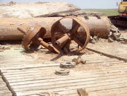
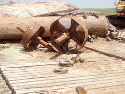
The uniform and familiar geologic conditions of the work site required minimal core sampling. Drilling of the main hole required repeated bores with increasingly large bits, ranging from an initial 6-in. tool up to 52 in. (Fig. 1). A Tensor Inc. wireless steering tool with TruTracker provided guidance for the bore operations, with bentonite used as the drilling fluid.
Troy rigged the pipe for pullback and positioned equipment for handling pipe into the borehole June 10. The swab, pullhead, and 100 ft of pipe were pulled into the hole the same day, with the bulk of the pull taking place June 11.
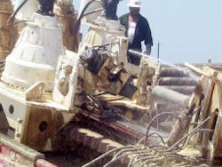
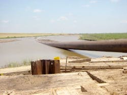
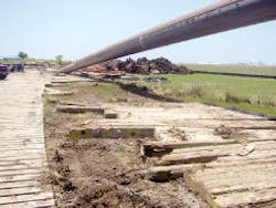
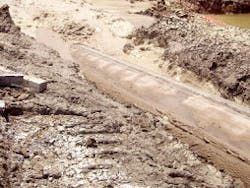
Laney used its own custom-built rig with 1.7 million lb of pull, as well as jerk capabilities, both to bore and move the pipe through the finished hole (Figs. 2-9). The total length of the pullback section was 6,200 ft, the extra joints added to clear the pipe fully from the marsh. The pipe entered the hole at 10° and exited at 8°.
Jetting injected mud into the hole, preventing any encroachment of the surrounding sandy soil. Mud motors were not used.
Laney described the pullback as the “largest mass” (combination of pipe length and pipe diameter) yet moved into place with HDD techniques.
Pipeline
The line consists of X-65 Grade steel with a 0.938-in. WT, 411.77 lb/ft weight, a pressure rating of 1,770 psi, and a maximum allowable operating pressure of 1,440 psi (to conform with US Office of Pipeline Safety Class 3 requirements). Freeport LNG says that normal operating pressure will be 1,250 psi.
Initial hydrotesting of the segment to 2,100 psi occurred after construction but before line-pull. Freeport LNG scheduled a second round of hydrotesting for after the pull. A final hydrotest will occur as part of testing the entire line.
Gas moving through the line will tie into the intrastate system near the Stratton Ridge salt dome. Companies currently shipping from Stratton Ridge include Kinder Morgan Inc., Enbridge Inc., Energy Transfer Partners LP, and the Dow Chemical Co., which also currently uses the dome for salt mining and storage.
ConocoPhillips Pipe Line Co. is also considering construction of a 42-in. line between Stratton Ridge and Iowa Colony, roughly 35 miles north, according to Freeport LNG, which plans to install a header capable of tying in up to 11 lines at Stratton Ridge.
The intrastate nature of the tie-in means that no separate pipeline rate or Federal Energy Regulatory Commission regulation of same needs to be established, the end of the new line instead being viewed as “the tailgate of the plant,” according to Freeport LNG.
All work on the pipeline is currently scheduled to be completed Nov. 7, 2006. The line will be filled with water until the regasification plant’s storage tanks are completed, with the 30 million gal of water held then being used to hydrotest the tanks. Draining and drying the line will precede its being filled with natural gas from the Stratton Ridge meter station. Freeport LNG will use this gas as start-up fuel once the terminal itself is ready to begin operations.
The high costs of permitting and mitigation involved if an overland lay had been attempted through the marsh balanced the extra costs involved in a pull of this scale. The pull option was also administratively and environmentally “friendlier,” according to Freeport LNG, limiting the number of potential delays encountered.
Freeport LNG
The Freeport LNG regasification terminal has been premitted to have an eventual capacity as high as 4 bcfd at 1,000 psi, with 1.5 bcfd planned for Phase 1. Phase 1 is scheduled to be complete in first-quarter 2008. Plans call for Phase 2 capacity, currently in FERC environmental assessment, to be operational by 2009-2010; 500 MMcfd coming online in 2009, with an additional 1-2 bcfd following in 2010, depending on market conditions.
Phase 2 will also involve installation of 7.5 bcf of salt cavern storage, with a peak injection-withdrawal of 750 MMcfd. A 24-in. line will run between this well and the 42-in. line.
