Steady-state models better predict waterflood frac results
A combination of analytical and numerical methods shows that the application of a pseudosteady-state solution to a steady-state problem invariably overpredicts the dimensionless productivity index (JD) and the benefits of hydraulic fracturing.
The goal of hydraulic fracture treatment design is to maximize the dimensionless productivity index (JD). Single-well, pseudosteady-state models used commonly in fracture treatment design fail to consider that a pattern waterflood is more nearly a steady-state flow regime.
More than half of the world’s oil reservoirs and more than 80% of Russia’s reservoirs are under waterflood. In many of these reservoirs, operators use improved hydraulic fracturing technology aggressively to increase producing rates from wells responding to pattern water injection.
Under the assumption of a single-well, pseudosteady-state flow regime, Mach presented a method for hydraulic fracturing that would improve pattern-waterflood well productivity in Western Siberia.1
More recently, Economides introduced a concept called unified fracture design with a goal of maximizing JDpss, again for a single-well pseudo- steady-state model.2 3 He implied while teaching this concept in Russia that it is universally applicable to all wells, including those responding to pattern waterflooding.
Reasonable values for JDss and the practical measures for maximizing it, as discussed in this article, differ from those derived for JDpss. This analysis is limited to either square drainage areas or optimally shaped rectangles and to the five-spot pattern in which the hydraulic fractures are parallel to the pattern edges.
Numerical solutions, as discussed, compared with several analytical solutions for specific conditions demonstrate equivalency and provide assurance that the results are accurate.
Analytical solutions for JD
The pseudosteady-state model assumes that reservoir boundaries are no-flow surfaces, where after an initial transient flow period, constant-rate production results in a constant change in volumetric average pressure with respect to time. This is the standard model applied for evaluating single-well pressure transient and fracture stimulation problems.
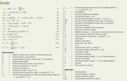
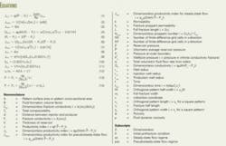
The pseudosteady-state productivity index (Jpss) is a simple performance index often used to describe the expected and actual improvement in fractured well performance (Equation 1 in the equation box). In Equation 1, JDpss is the dimensionless pseudosteady-state productivity index that is a function of drainage-volume geometry and fracture parameters.
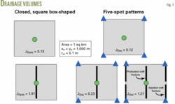
For an unfractured vertical well in the center of a square drainage area (Fig. 1), Equation 2 provides the pseudosteady-state dimensionless productivity index. The 0 subscript, in Equation 2, represents the prefracture initial condition.
For a vertical well centrally located within a square drainage area containing an infinitely conductive, fully penetrating (xf = ½ xe) vertical fracture (Fig. 1), Equation 3 gives the pseudo- steady-state dimensionless productivity index representing perfect linear flow.
Previous publications show the effect on JDpss caused by either infinite conductivity or finite conductivity fractures that only partially penetrate a square drainage area (xf < ½ xe) on the basis of either electric analog5 or numerical methods.6 7 As recently noted, these studies indicate that the maximum achievable pseudosteady-state dimensionless productivity index is about 0.9, assuming practical upper limits for fracture lengths and fracture conductivities.2
The steady-state model assumes that the flow in is equal to the flow out in each reservoir element. This is the standard model applied for evaluating multiple well, pattern, fluid injection projects.
For the case of an unfractured five-spot pattern (Fig. 1) with rw = rwi = rwp, Equation 4 gives the dimensionless steady-state pattern conductivity (QD0ss).8 9 In the equation, the 0 subscript again refers to the prefracture initial condition and Equation 5 is applicable.
By using the volumetric average pressure term rather than the external boundary pressure and dividing by 2π, the analysis can convert with Equations 6 or 7 the dimensionless steady-state pattern conductivity to a dimensionless steady-state productivity index for an unfractured five-spot pattern.
The analysis may use Equation 5 to develop analytical expressions for the dimensionless productivity index for fractured patterns in which either xf ≤0.2 xe or xf ≅ ½ xe when assuming an infinite fracture conductivity. In all other cases, the analysis must compute the volumetric average pressure numerically.
For a five-spot pattern containing infinitely conductive, fully penetrating (xf = ½xe) vertical fractures oriented parallel to the pattern edges in both the injection and production wells (Fig. 1), Equation 8 gives the dimensionless steady-state productivity index representing perfect linear flow.
Hagoort provides analytical solutions for dimensionless five-spot pattern conductivities, assuming infinitely conductive, partially penetrating fractures placed parallel to the pattern edges.9 Equation 9 applies to when either the injector or producer is fractured and propped (single fracturing). Equation 10 defines Sbp.
Equation 11 applies to when both the injector and producer are fractured and propped (double fracturing).
Hagoort’s solutions apply for dimensionless fracture half-lengths that are about <0.20 xe and are not valid for greater fracture penetrations.9
Numerical solutions for JD
All of the referenced analytical results assume that the fractures are open with an infinite conductivity. Numerical computations of the effect of finite fracture conductivity involve first using a finite-difference reservoir simulator to reproduce the analytical results and then simulating the effect of different levels of fracture conductivity (Fc), where Fc = (wf)(kf). The results are in terms of Fc rather than CfD (the dimensionless fracture conductivity) to see the effect of fracture length and proppant permeability more readily.
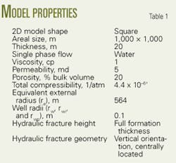
While CfD is a primary variable in a recently introduced physical optimization scheme for fracture design,2 this analysis has a different objective. The objective is the level of JD that may be reasonably anticipated as a result of executing a particular fracture treatment design. The analysis bases all the numerical results on single-phase flow of a liquid of small and constant compressibility through a homogeneous and isotropic porous medium (Table 1).
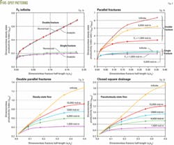
The analysis involved simulations with uniform square grids of 2,500, 10,000, 40,000, and 160,000 grid cells to represent a quarter of a five-spot waterflood pattern. Fig. 2 shows the convergence of the numerical solutions toward a dimensionless steady-state productivity index of 0.12 for an unfractured five-spot pattern.
The value of 0.12 is the Muskat analytical solution for a 1 sq km, five-spot pattern with equal injection and production well radii of 0.1 m.8 Note that even with 160,000 cells, the numerical solution does not converge to the analytical solution. The surprisingly high number of grid cells required for convergence in this type of problem has been previously reported.10
Fig. 3a compares the numerical solutions with 40,000 grid cells with Hagoort’s analytical solutions for both the single and double parallel-fractured five-spot. Unlike for the unfractured case, this reduced grid size seems adequate for computations of the fractured five-spot performance, owing to the presence of smaller potential gradients.
Fig. 3b shows the effect of parallel hydraulic fracturing on five-spot pattern productivity. The lower set of three curves is for the single fractured five-spot and the upper set of three curves is for the double fractured five-spot.
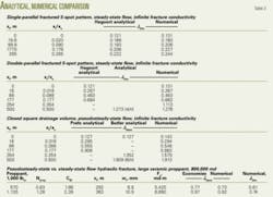
Each curve in a set of curves represents a different fracture conductivity. Where short and fully penetrating fractures occur, the numerical solutions agree well with the analytical solutions (Table 2). Where intermediate fracture penetrations occur, the analytical solutions do not apply, and in these cases the numerical solutions offer reasonably accurate substitutes.
Fig. 3c shows the dimensionless productivity index for the double-fractured five-spot as a function of dimensionless fracture half-length, where fracture conductivity is a parameter.
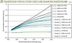
Fig. 3d shows the dimensionless productivity index as a function of dimensionless fracture half-length for five different levels of fracture conductivity for the pseudo- steady-state model. Again, as in steady-state flow, where short and fully penetrating fractures occur, the numerical solutions agree well with the analytical solutions (Table 2).
Maximizing JD
Not only is JD a strong function of fracture conductivity, fracture penetration and boundary conditions as described in this article, it is also a function of pattern aspect ratio,4 6 pattern type8 and pattern alignment. The maximum JDpss is 6/π for a square pattern shape. The JDpss of a fractured well in an optimally shaped rectangular pattern can reach levels of 10/π, or more.4
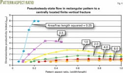
For the case of infinite fracture conductivity and a given orthogonal pattern area, the productivity depends upon fracture length and upon the aspect ratio (width/length) of the pattern. The curves in Fig. 4 used data from Suprunowicz and Butler on the basis of their numerical calculations for varying values of the parameters (A)/(L)2, ye, and xe, where A is the pattern area, L = 2xf is the full fracture length, and ye and xe are the pattern width and length, respectively.4 11
For any particular value of the parameter A/L2 (Fig. 4), the optimum aspect ratio is that where the pressure drawdown is a minimum, that is, where the JDpss is a maximum.
For very small values of A/L2, the patterns are long and narrow and the flow approaches the linear case. For very large values of A/L2, the optimum pattern shape approaches that of a square and the flow is radial.
The simple empirical Equation 12 can reasonably fit the optimum locus of the curves in Fig. 4, where xe = (A + L2)1/2 and ye = A/xe.4 11
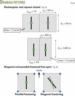
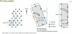
Fig. 4 shows the maximum JDpss of 6/π = 1.9 for a fully penetrating vertical fracture in a square drainage area, along with much higher JDpss’s for rectangular pattern shapes. Assuming a well pattern area of ½ sq km and a full fracture length of 707 m (Fig. 5a), the analysis shows that simply drilling wells on rectangular patterns having an aspect ratio of ½, rather than square patterns can increase JDpss from 1.9 to 2.8 (Figs. 4 and 5a).
Fig. 5b shows two extreme fracture orientations: the parallel fracture used to derive the results presented in this article and the diagonal fracture. The diagonal fracture runs in the direction N45°W from the injector towards the producer or vice versa. Whereas long parallel fractures may increase five-spot sweep efficiency, diagonal fractures may severely reduce it where xf>0.175xe for single fracturing and xf>0.085 xe for double fracturing.9
Fig. 6 shows the effect of pattern alignment on JDss for a parallel fractured five-spot where both the injectors and producers are fractured. Given a field development where the patterns align in a north-south direction and the hydraulic fractures propagate N22½°W along a heading perpendicular to the least principal stress direction, JDss is about 0.75 for the conditions of unit mobility ratio displacement, xf = 0.175xe and Fc = 5,000 md-m.
Simply determining the hydraulic fracture azimuth at the beginning of field development and aligning the patterns parallel to it are practical measures shown to be capable of increasing JDss from about 0.8 to 1.2, or by 50%.
Results
Numerical results for the models that contain only fractured wells compare closely with the analytical results for short and long fractures (Table 2). This confirmed agreement suggests that JDpss values derived and used in earlier work1-6 (Table 2) are overstated by about 5-10%, presumably because of the use of overly coarse finite-difference grid systems.10
Where intermediate-length fractures are present, the analytical solutions do not apply and the numerical solutions provide the missing information.
When an unfractured well is present, as in the singly fractured five-spot or when xf = 0 in the other cases, the analysis has steeper potential gradients and requires more grid cells than 160,000 for reasonably accurate numerical solutions. The numerical models overpredict both JDss and JDpss by about 10% when an unfractured well is present.
Analytical solutions for a fully penetrating fracture of infinite conductivity set the upper limit for JDpss at 6/π, JDss at 4/π for the doubly fractured five-spot and JDss at π/14 for the singly fractured five-spot.
Numerical solutions in Figs. 3b and 3c match the endpoint values of 6/π and 4/π, respectively, and further demonstrate that JDss << JDpss over the full range of fracture penetrations, the difference becoming greater with increasing fracture conductivity. JDss values in Table 2 for large, high-permeability fracture treatments are about 30% lower than their JDpss counterparts,3 where the JDss values represent productivities from doubly fractured five-spot systems.
An important point is that steady-state flow has less productivity per unit area of reservoir, despite doubling the total stimulation costs as a result of fracturing both injection and production wells.
Fig. 7 shows the progressive reduction in the dimensionless productivity index as the flow regime changes from transient to pseudosteady-state and then on to steady-state flow. These results are from a simulation of a fractured well with xf = ½ xe before and after starting water injection while producing at a constant production rate. The increased pressure drop required during steady-state flow as compared to pseudosteady-state flow causes the reduction in dimensionless productivity index from 6/π to 4/π, as show in Fig 7.
This is the point of this article.
Equation 13 describes the linear steady-state flow to a fully penetrating, infinite conductivity vertical fracture maintained at a pressure of Pw and at the center of a square drainage area. In the equation, q is the total flow to the fracture, whereas q in Equation 14 is for a linear, pseudosteady-state flow.
As Butler explains, in the steady-state problem the reservoir boundaries are the source of the produced fluid and the pressure rises linearly with x on either side of the fracture.4 In pseudo- steady-state flow, after production passes the initial transient phase, pressure everywhere in the reservoir falls at a constant rate and the oil arising from expansion adds to the stream flowing to the fracture. In this case, the reservoir boundaries become no-flow surfaces rather than the source of the produced fluid and the flow increases linearly as it moves to the fracture.
Equation 14 differs from that for steady-state flow (Equation 13) by the inclusion of the quadratic term. Near the well, this has little effect, but it becomes increasingly important as the pressure transient approaches the boundaries. The pressure gradient drops to zero at the boundary.4
The major difference shown in Fig. 4 between single and double fracturing requires an explanation. The single fracturing formula (Equation 9) contains both well radius and fracture half-length, whereas the double fracturing formula (Equation 11) contains the fracture half-length only. As Hagoort explains, flow resistance is concentrated at the injection and production wells.9 In a five-spot, both injector and producer contribute equally to the total flow resistance. Hydraulic fracturing one well is therefore taking only half measures.
Fig. 8 shows the difference between JDpss and JDss and the importance of effectively fracturing both the injectors and producers in a pattern waterflood.
JDss has about a 0.2 limit unless the five-spot flood pattern is doubly fractured, regardless of the volume and permeability of the fracture proppant. Maintaining borehole pressures that initiate and grow the injection well hydraulic fractures is the single most cost-effective measure for maximizing JDss.
Item to consider
Following are items to consider when designing fracturing treatments for pattern waterfloods:
- The design needs to shift its focus from single wells to the repeated single and multiple-well patterns used for primary depletion and waterflood programs.
- Application of JD in pattern development programs calculated on the basis of single-well pseudosteady-state models will overstate productivity, confound results, and lead to unwarranted refracturing efforts. A model having boundary conditions most like those of the field will establish a common expectation between operators and suppliers for the achievable level of JD.
- In square patterns, the theoretical maximum JDpss is 6/π. The use of optimally shaped rectangular patterns may increase the theoretically reachable JDpss to 10/π, or more.
- JDss is much less than JDpss (JDss << JDpss) over the full range of fracture penetrations, the difference becomes greater with increasing fracture conductivity and penetration, reaching 50% at the theoretical limits and 30%, or more, at practical fracture conditions.
- The theoretical maximum JDss is 4/π for the five-spot flood pattern where both the injectors and producers are fractured. JDss is limited to about π/14 for the five-spot pattern where only the injector or producer is fractured.
- Aligning the five-spot flood pattern parallel to the hydraulic fracture azimuth is capable of increasing JDss by 50%, or more.
- Maximizing the JD involves determining hydraulic fracture azimuth at the beginning of field development, creating long, highly conductive fractures, and laying out optimally shaped rectangular patterns parallel to the fracture azimuth.
Acknowledgments
The author thanks Robert Holtslag, Jose Rueda, and Jorge Manrique formerly with Yukos Oil Co. and Allan Sibbit of Schlumberger Inc. for their discussions on the need to distinguish between JDpss and JDss.
References
- Mach, J.M., et al., “Big Wells from Effective Fracturing in Russia,” Oil and Gas Exhibition and Technical Conference, Moscow, June 17-20, 2003.
- Economides, M., et al., Unified Fracture Design, Bridging the Gap Between Theory and Practice, Orsa Press: Alvin, Tex., May 2002.
- Demarchos, A.S., et al., “Pushing the Limits in Hydraulic Fracture Design,” SPE Paper No. 86483, SPE International Symposium and Exhibition on Formation Damage Control, Lafayette, La., Feb. 18-20, 2004.
- Butler, R.M., Horizontal Wells for the Recovery of Oil, Gas and Bitumen, Canadian Institute of Mining, Metallurgy & Petroleum, Petroleum Society Monograph Number 2, Topline Printing, 1994.
- McGuire, W.J., and Sikora, V.J., “The Effect of Vertical Fractures on Well Productivity,” Transactions AIME, No. 219, 1960, pp. 401-03.
- Holditch, S.A., Quarterly Low-Permeability Gas Well Research Report for Fall, 1975, Texas A&M University, College Station, Tex.
- Gidley, J.L., et al., Recent Advances in Hydraulic Fracturing, SPE Monograph Vol. 12, 1989, pp. 322-24.
- Muskat, M., Flow of Homogeneous Fluids in Porous Media, J.W. Edwards, Inc., Michigan, 1946.
- Hagoort, J., Waterflood-Induced Hydraulic Fracturing, dissertation, Delft Technical University, April 1981.
- Dietrich, J.K., and Kuo, S.S., “Predicting Horizontal Well Productivity,” Journal of Canadian Petroleum Technology, Vol. 35, No. 6, June 1996.
- Suprunowicz, R., and Butler, R.M., “The Choice of Pattern Size and Shape for Regular Arrays of Horizontal Wells,” Journal of Canadian Petroleum Technology, Vol. 31, No. 1, January 1992, pp. 39-44.
The author
James Dietrich (dietrichcorp @dc.rr.com) is a consulting reservoir engineer with TDC-Dietrich Corp., presently providing reservoir engineering services to Chevron (Offshore) Thailand Ltd. in Bangkok. He previously worked for Shell Oil Co., Shell Development Co., and Todd, Dietrich and Chase Inc., where he was involved with thermal recovery and reservoir engineering projects. Dietrich holds a BA in geology and an MSc in engineering from the University of California, Berkeley.
