New method sets concrete coating’s effect on pipeline stiffness, stress
Alexander Aynbinder, Technip USA, Houston
The thickness of concrete coating on a large-diameter offshore pipeline may be up to eight times the wall thickness of its steel pipe, requiring that its effects on the stiffness, stresses, and strains of the line as a whole be understood as precisely as possible.
Concrete coating of offshore pipes increases a pipeline’s specific gravity, ensuring that on-bottom stability is not affected by environmental loads. One existing calculation procedure, used in calculating stresses and deflections, assumes the external concrete coating increases the weight but does not contribute to bending stiffness. The other current method considers the effective bending stiffness but uses a simplified approach based on a given linear concrete stress distribution in a pipe cross-section and the assumptions that the compressive strength is not limited and the tensile stresses can be neglected.
The first method underestimates the actual stiffness of concrete pipe; the second exaggerates it.
This article presents a more precise numerical iterative method of determining bending stiffness, stresses, and strains, taking into account the nonlinear mechanical properties of steel and concrete.
The effective bending stiffness of concrete-coated pipe depends considerably on the concrete coating strength and the applied bending moment. Because the bending moments vary along the pipeline, it is extremely important to consider them in offshore pipeline laying programs and in the assessment of offshore pipeline free spans.
The bending moments also depend on bending stiffness, the two being interrelated in any statically indeterminate system. The nonlinear method of stiffness and stress analysis presented here bears this in mind and offers significant cost and safety improvements in the design of concrete-coated offshore pipelines. The method also enhances the reliability of such pipeline systems by offering a more accurate determination of the coating’s influence on the pipeline’s deflected mode.
Material properties
The mechanical properties of steel and concrete determine the distribution of stresses and strains and the total effective stiffness of concrete-coated pipe
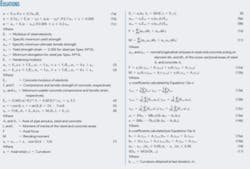
• Steel. Limit-state criteria often guide the design of offshore pipelines. A set of three equations based on the pipe’s standard characteristics describes the proposed model (Equations 1a-c in accompanying equation box).
Steel’s stress-strain diagram consists of three sections.
The first section of the stress-strain diagram is linear and conforms to traditional engineering and methodologies of pipeline codes. The corresponding slope of this line equals the modulus of the elasticity of steel. This part of the diagram remains valid to the limit of proportionality between stresses and strains.
A curve that continuously and smoothly connects to the first and third linear section of the diagram describes the second section.
The third section of the diagram is linear. The corresponding slope of this line equals the hardening modulus. This part of the diagram extends to ultimate strength from yield strength.
• Concrete. Typical stress-strain curves of concrete are essentially nonlinear. The stress-strain diagram is tri-linear, having different parameters of maximum concrete strength and maximum usable strain for compressive and tensile areas. Even though tensile strength of concrete is small, considering it allows obtaining a general solution and introduces the possibility (if required) of using reinforcing cages.
Traditional engineering and the methodology of the ACI Building Code-that the first part of stress-strain curves is linear-divide concrete’s proposed stress-strain diagram into three sections.
The first section of the diagram is linear, with a tangent of slope equal to the modulus of elasticity of concrete, and stresses up to maximum strength.
The second section is also linear, with a tangent of slope equal to zero, strains up to maximum usable strain, and constant stresses equal to concrete strength.
The third part illustrates that stresses equal to zero as strains pass maximum usable limits.
Equations 2 and 3 provide concrete model relationships for compressive and tensile areas, respectively. Compressive strength (fc'), compressive usable strain (εuc), and density of concrete (wc) most often determine properties of concrete in offshore pipeline design. Equation 4 establishes the other parameters used in Equations 2 and 3. Equation 4 is empirical and uses MPa as the modulus of elasticity and strength and kg/cu m as its measure of density.
Methodology
Multiplying the elasticity modulus and inertia moment determines stiffness of a pipe section in linear theory of material strength. Concrete-coated pipe consists of bare steel pipe and concrete. Investigating stiffness of this composite section requires considering both concrete’s nonlinear nature and differences in its tensile and compressive strengths. At the level of stresses in steel, concrete exhibits strong inelastic behavior and its stresses often exceed its strength.
Kinematics assumes that the plane sections through the beam (normal to its axis) remain planar after the beam is subject to stress and that strain varies linearly with distance from the neutral axis. This assumption provides the basis for considering a pipe’s non-linear properties.
Because stress and elastic modulus are interrelated, solving the problem requires iterative numerical analysis with the division of the annulus of steel and concrete on a finite number of areas.
The first iteration sets the effective moduli of all areas at equal to the elastic modulus of both steel and concrete. Subsequent iterations modify these values for all areas based on the evaluated level of strains associated with every area. On each iteration, the nonlinear stress-strain diagram of these materials computes the secant moduli of steel and concrete, treating them as an elastic constant. Secant moduli modify the stiffness.
The axial force, F, and moment, M, generally act on a pipe section. If bending moments in the plane of the pipe section (Mx) and out of the plane (My) occur, the resulting bending moment is M=(Mx2 + My2)1/2 because the pipe has vertical and horizontal axes of symmetry. An angle to previously coordinate the system, y0z, equal to arctan(Mx/Mz), defines the new coordinate system. The geometry of the composite section describes the steel area with mean radius rs and thickness ts and concrete area with mean radius rc and thickness tc.
To use the finite-element method, the pipe’s cross-section is divided into n elements with i as an index ranging from 1 to n . Stresses in the elements are constant. Equation 5 determines the location of every i-th element in the u0v coordinate system, where the index i ranges from 1 to n and the value of r is equal to rs or rc for the steel or concrete areas, respectively.
The beginning of iteration (iteration j = 1) assumes that the effective moduli of steel and concrete are the same as that of linear material. Equation 6 calculates the pipe axial strain (εfo) and curvature (ko) at iteration j = 1. Equation 7 determines the longitudinal strain (εij) in each i-th element for every j-th iteration, in accordance with kinematics.
After calculating longitudinal strain with Equation 7, Equations 1-3, describing the relationship of stresses and strains between them, determine the stresses for each i-element of steel and concrete produced by the above-strain.
Equation 8, based on the stresses and strains found in the previous iteration, calculates the secant moduli of steel and concrete. Equation 9 calculates the normal stresses in steel and concrete areas as a function of axial strain (εfj), curvature (kj), and the secant moduli of steel (Eij(s)) and concrete (Eij(c)).
Equations 10 and 11 calculate the axial force and bending moment from the static condition of equilibrium. Substituting the values of σij calculated by Equation 9 into Equations 10 and 11 yields a system of two linear equations (12a-b), with εfj and kj unknown.
Equation 14 shows the solution to Equations 12a-b, after which iteration starts from Equation 7, with the values determined by Equation 12. Equation 16 writes the criteria of iteration process convergence.
The result of εfj and kj in the final iteration calculates concrete-coated pipe stiffness and stress distribution in the steel and concrete areas. Equation 17 determines the bending stiffness of concrete-coated pipe, with the cross-section distribution of stresses and strains calculated by Equations 9 and 7, respectively.
Application
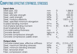
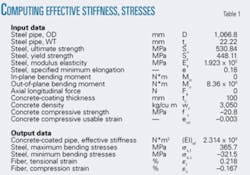
Data from a typical 42-in. offshore pipeline illustrate the application of this new method. Table 1 presents the results of calculations performed in this application by a new spreadsheet program.
The value of the active bending moment in this example produces the maximum-minimum longitudinal stress in bare steel pipe equal to the yield stress of the steel (448 MPa). Concrete about five times thicker than the WT of bare pipe coated it. The coating reduced the absolute steel bending stresses to 366 and 322 MPa in tensile and compressive areas, respectively. The stiffness of concrete-coated pipe increases 20% to 2,319 MN*m2 from the 1,914 MN*m2 of bare steel pipe.
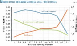
Fig. 1 illustrates the results of further study into the effect of active bending moments on changes in stress and stiffness of 42-in. OD × 0.875-in. WT pipe covered with 100 mm of concrete. The “relative bending moment” (X-axis) reflects the ratio of active bending moment to the yield moment (the moment resulting in yield bending stress in the bare pipe). The actual bending moment increases stiffness in the interval to 2.0 from 1.2.
The simplified method and the empirical formula recommended by DNV yield bonded effective stiffnesses of 1.6 and 1.85, respectively. These values are independent of the bending moments.
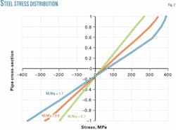
Fig. 2 shows the steel longitudinal stress distribution of three relative bending moment values of 1.1, 0.9, and 0.7 in a cross-section of the 42-in. concrete-coated pipe. The reduction levels in steel bending stress manifest themselves more significantly in the compressive area of a steel pipe than in the tensile area. The difference between concrete’s compressive and tensile strengths caused a shift in the neutral axis.
null
Bibliography
Desai, S., and Abel, J., “Introduction in the Finite Element Method: A Numerical Method for Engineering Analysis,” Van Nostrand Reinhold Co., p. 198, 1972.
DNV-RP-F105-2002, “Free Spanning Pipelines,” Det Norske Veritas, p. 39, 2002.
Leet, K., “Reinforced Concrete Design,” Second Edition. New York: McGraw-Hill Inc., 1991, p. 646.
Mousselli, A.H., “Offshore Pipeline Design, Analysis and Methods,” Tulsa: PennWell Books, 1981, p. 192.
Editor’s Note: The author developed this article while employed at J. Ray McDermott.
