Well repair required analysis of multiple scenarios
Wathik M. Alhashimi, Arabian Gulf Oil Co.,Benghazi, Libya
Repair of a casing leak on a well in the Magid field in eastern Libya required engineers to examine multiple scenarios for what may have caused the failure.
Their hands-on experience, adequate well-testing procedures, proper follow-up of operations performed during initial completion, in-depth study of the well’s drilling history coupled with engineering interpretations all suggested that the well had multiple damage that occurred during or after drilling operations.
Arabian Gulf Oil Co. (AGOCO) operates Well Z7-80 in the Magid field and noted the leak in the 9 5/8 in. intermediate casing during the initial completion work.
Further investigations indicated that this well also sustained damage in the bottom third of the 9 5/8 in. casing string.
AGOCO engineers first determined various scenarios that may have caused this failure and then screened them out with tests and follow-up observations until they obtained a single most-plausible scenario.
After the engineers verified this scenario during well-repair procedures, the well was repaired and completed.
Drilling summary
AGOCO requires the drilling rig to be released after drilling a production well. The company then moves in a workover rig to complete the well. While waiting for a workover rig, the well is tied in to a gathering and separation station.
The period between the end of drilling and initial completion could range from 1 to 3 years and depends on AGOCO’s priorities and production schedules.
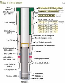
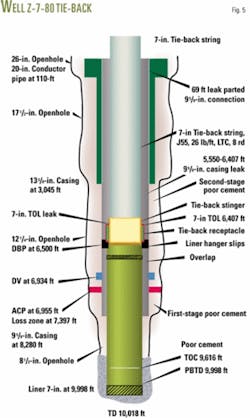
AGOCO drilled Well Z-7-80 in early 2004 (Fig. 1) and started the initial completion operation in late 2005. This work detected a leak at the top of the 9 5/8 -in. production casing.
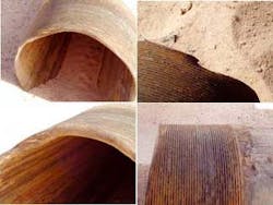
Wellhead inspection revealed that the 9 5/8-in. casing had parted at a depth of 69-ft from the rotary table. The recovered separated pin suggested a connection failure which had suffered repeated banging caused by upward dynamic forces (Fig. 2).
A review of the drilling history of this well failed to determine why the 9 5/8-in. casing had failed.
During drilling of the 12¼ in. hole, the borehole experienced complete losses at 7,379 ft and the remainder of the 12¼ in. hole to 8,280 ft was drilled blindly while completely losing the 8.35-ppg drill water to a Paleocene thief zone.
The well has 9 5/8-in. casing, fitted with a differential valve (DV) and an annular casing packer (ACP), run and cemented in two stages. The casing string would have weighed 331,200 lb in air; while casing wet weight, assuming a 50% hole evacuation, was about 295,000 lb and with 25% evacuation would have weighed 281,000 lb.
The 9 5/8-in. casing was run and cemented in two stages: The drilling report, however, indicates no cement was recovered at surface upon displacement of both stages. The cement work involved setting the ACP by bumping the cement plug at the end of the first stage then opening and closing the DV after finishing the second-stage cementing.
The 9 5/8-in. casing landing weight after cemented was only 40,000 lb. This low weight made the completions engineers look closely at the 9 5/8-in. casing operations because of the possibility that 9 5/8-in. casing parted during or after the drilling of the 8½-in. hole.
The engineers analyzed various failure scenarios and developed a most plausible scenario that could have caused such an event. They also needed to verify the scenario before embarking on a costly repair job to ensure a reasonable success potential.
The parting of the casing, under such a high tension load and with the parting point close to surface, would have caused the rest of the casing to drop downhole. This would have caused a cyclic loading of compression and tension on the casing due to potential elastic forces (spring effect) that would have subjected the bottom third of the casing to forces acting at the weakest points (connections). These forces would cause thread overlapping and slipping, assuming that the 9 5/8 -in. casing was unsupported.
The upward traveling force would dampen due to friction with the wellbore. If the casing was supported by cement sheaths, however, this phenomenon would not take place.
The condition of the recovered 9 5/8-in. pin partially supported the scenario. Casing failure would subject this pin to banging due to dampened forces from the lower part of the casing acting as a spring.
The cement bond log (CBL) and variable density log (VDL) obtained during the initial completion also indicated nil to poor cement around the 9 5/8 -in. casing (both stages).
The engineers, however, could not rule out the possibility of the 9 5/8 -in. casing parting during the drilling of the 8 ½-in. hole. This would not have put the casing in a spring effect for the cement or stagnant annular content (gelled mud, cuttings, etc.) around the 9 5/8-in. casing, however weak, would have taken most of the casing tension loads.
The 13 5/8 in., 3,000-psi casinghead would have held the 9 5/8-in. casing and the casing hanger when landed properly and not allow it to come free and held only by the secondary seal of the upper 13 5/8 by 11 in., 3,000-psi adapter spool.
The engineers also could not rule out the possibility that the 9 5/8-in. casing hanger was unlanded, during the parting event, by the upward banging force caused by the casing spring effect because the drilling history indicated improper landing at 40,000 lb and normally, the elastic forces act mostly on the bottom third of the casing and are dampened as they travel up-hole. These forces could have caused the damage in the recovered pin because the recess in the bottom of the 13 5/8-in. 11-in. 3,000 psi adapter spool just above the secondary seal cavity restricts the stub of the 9 5/8-in. casing from upward movement.
The well’s drilling history indicated that the completion work encountered problems in setting and cementing the 7-in. production liner (J-55, 26 lb/ft, long threads and coupling (LTC), 8 threads/in.). This liner, during running operations 40 ft off bottom, was forcibly worked down to bottom; however, the liner hanger could not be set and became stuck off bottom.
The history indicated that the running string (5 in., 19.5 lb/ft, E drill pipe) was over tensioned by 100,000 lb above its wet weight in attempts to release the sticking liner with no success; therefore, the liner landing weight was reported as 60,000 lb. The actual liner wet weight in 9.3 ppg mud should have been 75,000 lb; therefore, part of the liner was left in compression, for example if the liner was not set.
The report says this liner was cemented with 70 bbl of lead slurry and 41 bbl of tail slurry and then displaced with 255 bbl. The plug was not bumped after displacement of the cement slurry.
Because the 7-in. liner capacity was 137 bbl and the running string capacity was 113 bbl, or a total 250 bbl, the cement plug was not bumped, and 379 ft of set cement were found inside the 7-in. liner (15 bbl) during initial completion, it was clear to AGOCO engineers that the 7-in. liner was under-displaced.
Even so, 96.4 bbl of pumped cement slurry in the 8 ½-in. hole and 7-in. liner annulus should have filled about 4,267 ft of in-gauge annulus to 5,731 ft kelly bushing, not considering washouts.
The well’s drilling history, however, indicated that no cement was obtained at surface while reverse circulating through the liner running string upon its release. Moreover, the CBL-VDL obtained during initial completion indicated poor cement over only the reservoir zone (9,995-9,500 ft), and thereafter a free 7-in. liner to the top of the liner (TOL).
Because the first-stage cementing job of the 9 5/8-in. casing was also questionable and the 7-in. liner was not completely cemented (free pipe from 6,407-9,500 ft, empty overlap 7-9 5/8-in., leaky 7-in. TOL, and leaky 9 5/8-in. casing from 5,500-6,400 ft), the engineers concluded that the Paleocene was dumping its H2S water throughout the initial completion either through the damaged 9 5/8-in. casing connections somewhere in the bottom third of the 9 5/8-in., in the overlap intervals, or around the 9 5/8-in. casing shoe into the overlap into the wellbore, provided the 9 5/8-in. annular casing packer (ACP) was set properly.
Initial completion
The well reentry work during the initial completion operations indicated a leak in the well because applied pressure into the wellbore bled off from 500 to 100 psi in 1 min.
Cleaning operations inside the 7-in. liner tagged the top of cement (TOC) inside the 7-in. liner at 9,616 ft, thereby indicating that 379 ft of underdisplaced set cement (15 bbl) was left inside the 7-in. liner. The work also circulated out H2S Paleocene water while drilling out the cement.
The engineers provided test procedures to define the leaking intervals. The first step tested the unperforated 7-in. production liner using a 7-in. test packer set below the 7-in. TOL. The test pressure to 500 psi indicated that this section was not leaking.
The next step involved cleaning and scrapping the 9 5/8-in. casing with a 9 5/8-in. casing scraper to ensure re-enterablity and to prepare this casing for pressure testing with a 9 5/8-in. test packer run and set above the 7-in. TOL.
Pressure testing indicated a leak in the 7-in. TOL (pressure bleeding off from 500 to 50 psi in 15 min). H2S Paleocene water was circulated out throughout cleaning operations.
The engineers suspected wellhead problems and had the 13 5/8-in. by 11-in., 3,000 psi adapter spool nippled down. The secondary seal of this adapter, however, held the retrieved 9 5/8-in. casing hanger, 9 5/8-in. landing joint, and the joint below it ( pin looking down).
The parting point was found at 69-ft RT. This indicated that the 9 5/8-in. casing was not landed properly during the cement job and the 9 5/8-in. casing connector at 69 ft suffered a mechanical failure.
The examination of the recovered 9 5/8-in. casing pin showed that the lip of the recovered 9 5/8-in. pin was severely damaged, banged, bent inward and outward below the 8 ½-in. and beyond the 9 5/8-in. diameters. The pin seemed to have suffered repeated banging (bent in various spots), partially over the circumference of the lip.
The engineers also noted that only the top 11 threads of the recovered pin connection were engaged while the balance of this connection had no signs of engagement.
Attempts to tie back the 9 5/8-in. to surface, by running a new 9 5/8-in. casing joints, failed and the leak persisted at the 69-ft depth.
The CBL-VDL run inside the 7-in. liner revealed poor cement over the reservoir and uncemented liner above. The CBL-VDL inside the 95⁄8-in. casing up to the DV revealed bad cement throughout with faulty first and second-stage jobs.
A pressure test with a 7-in. test packer run in the 7-in. production liner found the liner to be sound.
Further testing of the 9 5/8-in. intermediate casing with a 9 5/8-in. combination tool showed that the casing leaked from 5,550 to 6,400 ft with good casing between 1,400 and 5,550 ft.
Based on engineering analysis and interpretation of the observations made and the results obtained from testing and because the entire 95⁄8-in. casing was reenterable (as proved by the scraping and packer’s job), the engineers decided to run a 7-in. tie-back string.
The 7-in. TOL dressed with an 8 ½-in. taper mill went to 6,407 ft and a 7 3/8-in. polish mill went to 6,410 ft. Returns obtained during these operations, however, still included H2S Paleocene water, indicating dumping from behind the 9 5/8-in. casing. The cleaning string (3 ½-in., J55, 9.3 lb/ft EUE tubing) also had become black in color, suggesting H2S embrittlement.
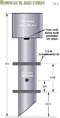
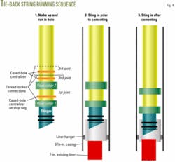
Two events occurred close to the 7-in. TOL while the rig ran the 7-in. tie-back string (Figs. 3 and 4). The first was that the string experienced a drag of 25,000 lb between 6,360 and 6,407 ft, and the second was that the tie-back string become stuck every time it got to 6,410 ft. It required a 20,000 lb over-pull to become free.
These problems may have resulted from:
- The tie-back stinger hanging into a damaged 9 5/8-in. casing connection at a depth below 6,360-ft.
- The stinger with two 7 ½-in. ribs may have hung up inside the tie-back receptacle, which has a 7 5/8-in ID.
Because the work required that the cement of the 7-in. tie-back string be brought to surface to resolve the leaky 7-in. TOL and leaky 9 5/8-in. casing, engineers had to analyze the following:
- The high hydrostatic head that the cement slurry would impose because the combination of friction pressure losses during cementing operations may break down the formation below the 9 5/8-in. casing shoe.
- The Paleocene water may contaminate the cement slurry causing it to flash set or to become too viscous to pump; hence, the work may pump-off the tie-back stinger.
- The leaks in the 9 5/8-in. casing could cause losses into the poorly cemented loss zone behind the 9 5/8-in. casing.
Cementing techniques analyzed included:
- Cement the tie-back string in one stage with light lead slurry followed by a small volume of Class G tail slurry.
- Cement in two stages, however, the stage collar would introduce a weak point in the tie-back string.
- Short cementing: pump good cement between 6,400 and 5,500 ft. The leak at 69 ft, however, had to be repaired by a top cementing job.
The engineers selected the first option.
The work involved circulating around the tie-back string while the stinger was partially inside the receptacle. Next the string was cemented in a single stage with 182 bbl of lightweight 13.2-ppg cement lead slurry, followed by 16 bbl of 15.8-ppg Class G tail slurry.
A total of 245 bbl of water displaced the cement with partial slurry loss experienced after pumping 132 bbl.
After the displacement of the cement, the next step involved running the 7-in. tie-back stinger completely inside the receptacle and applying a 5,000-lb weight on the 7-in. TOL. This was followed by landing the 7-in. cemented tie-back string and then cleaning out and successfully pressure testing the string (Fig. 4).
The well on test flowed at more than 1,500 bo/d after perforating the reservoir zones.
The author
Wathik M. Alhashimi is a senior engineering specialist-drilling, completions, and workovers for the Arabian Gulf Oil Co., Benghazi, Libya. He resides in Calgary. Previously he worked in management and engineering for several other petroleum and oil field service and supply companies in Canada, South America, and the Middle East. Alhashimi holds an MS in petroleum engineering from the Petroleum, Gas, and Geology Institute, Bucharest. He is a member of the Association of Professional Engineers, Geologists, and Geophysicists of Alberta.
