Engineers consider wear in designing new casing strings for Tarim field
Gao Zhihai, Xi’an Jiaotong University, Xi’an City, China
A new method to design casing strings is based on predicted and actual wear of strings in the Tarim oil field, China.
Casing wear during drilling reduces casing strength, especially collapse strength, which represents a safety hazard. This article presents a method of casing-string collapse strength design considering wear based on the prediction on casing wear and the remaining collapse strength of the worn casing. Software for casing string design was developed, applied, and validated, showing that the method may avoid worn casing collapse with good economy.
Casing wear in China
In Chinese oil fields, especially in the Tarim field, wells are usually deep or super-deep and drilling usually takes 1-2 years. It is inevitable that casing wear develops from drill pipe rotation and tripping.
Casing wear is a severe problem and reduces casing string performance. A special problem is collapse resistance, which threatens the safety of the well. For example, severe wear led to the collapse of intermediate casing of 244.5-mm-diameter in the YangXia No 1 well in the Tarim oil field in 1997. As a result of the accident, the well was abandoned and 100 million RMB yuan ($12.5 million) was lost.
In order to minimize wear from the drill string, engineers take certain measures in wells where casing wear is a potential problem. For example, they try to optimize drilling parameters, keep dog-legs to a minimum, install rubbers, keep sand and silt content in the mud as low as possible, and so on. But the best way to design casing strings and prevent the collapse of worn casing may be to consider the effect of wear on casing collapse resistance.
Traditionally, casing string design has been based on the string types and functions. Generally, there are four types of casing strings: conductor, surface, intermediate, and production. Casing wear usually occurs in the intermediate casing string.
When collapse strength of intermediate casing was studied, the worst load conditions were taken into account. The combination of loads was calculated and the results compared with strengths that were based on the selection of safety coefficient. But the effect of wear on casing collapse strength isn’t considered in standard casing design.1
By investigating casing wear problems in China’s oil fields, we found that the effect of wear on casing collapse resistance was not taken into account when casing string design wear done for the lack of standard of casing string design that considered wear effect.
The problem of casing wear is severe and ubiquitous. The author investigated eight deep wells in different areas of Tarim oil field. Three wells exhibited severe casing wear: Quele No. 1, Dongque No. 8, and Kubei No. 1. Some of the casing was even worn through.
After research of the wear problem in deep wells, this article presents an equation to predict remaining collapse strength of worn casing, validated by finite-element analysis (FEM) and full-scale collapse testing of worn casing. The prediction equation offers good precision.
Based on the prediction of casing wear and remaining collapse strength of worn casing, the author presents a new method of casing string design that considers effect of wear on casing collapse strength and that led to the development of software for wear casing string design.
Predicting casing wear
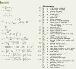
Jerry P. White and others developed the formula of estimated casing wear by use of the linear wear model.2 Equation 1 estimates the volume of metal removed by wear (see equation box).
Prediction of field casing wear usually begins with a measured or expected dogleg. For a given dogleg, Equation 2 provides a simple means of calculating the side force.
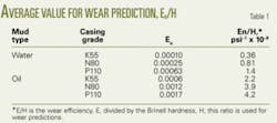
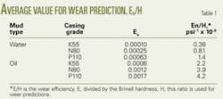
Table 1 shows wear efficiency and E/H, based on White.2
Comparing predicted and measured casing wear in the Quele No.1 well in the Tarim oil field validated the precision of the formula.
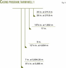
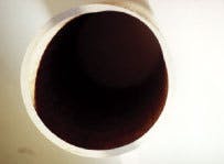
Quele No.1 is an exploratory well, designed to reach 5,695 m. The well was actually drilled 163 m deeper, to a total depth of 5,858.34 m. The casing program is shown in Fig.1. Drilling began Sept. 11, 2000, and ended Oct. 9, 2001. During drilling, severe wear occurred in the upper part of the 9 5/8-in.-diameter intermediate casing, as shown in Fig. 2. Ultimately, 7-in.-diameter production casing was required, tied back to the wellhead.
Casing wear volume of the Quele No.1 well was calculated using White’s formula.2 The predicted volume of casing wear was 13.14 cu in./ft and the actual volume was measured at 14.01 cu in./ft. The difference is only -6.27%. (The negative sign means that the predicted value is lower than the actual.) Based on this single data point from the Tarim field, White’s formula appears to be fairly accurate in predicting casing wear.
Predicting collapse strength
Predicting the remaining collapse strength of worn casing begins with examining actual wear patterns.
Casing wear can occur in various patterns, but all the significant wear observed in the Tarim oil field wells occurred as crescent-shaped wear and 50% of all of the recovered casing was worn in this manner.3 After measuring the worn casing taken from the Quele No.1 well, we found that the shape of worn casing is crescent-shaped (Fig. 2).
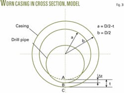
During drilling, friction occurs between drill pipe and casing. Fig. 3 is a diagram depicting a cross-sectional profile of worn casing. The author developed Equations 3-6 to calculate the remaining collapse strength of worn casing. Actual, unworn tube collapse strength was estimated using Tamano’s empirical formula.4
To validate Equation 6, full-scale collapse testing and FEM analysis of worn casing was done at the Tubular Goods Research Center, Xi’An, China. Common P110 casing with diameter 244.5 mm x 11.99 mm was selected for the test.
The collapse testing was performed in a full-scale collapse test machine. The sample was subjected to a load representing only outer pressure.
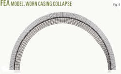
FEM analysis on worn casing collapse strength was done with MSC/NASTREN software. Fig.4 shows the model of worn casing collapse. The data used in the analysis are from measured casing samples.
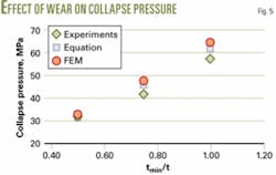
The comparison of the estimated pressure that was calculated by Equation 6, the results of FEM analysis, and experimental results indicate good agreement (Fig.5). Therefore, we believe Equation 6 can be useful in casing string design that takes account of the effect of wear on casing collapse strength.
null
Design, considering wear
The design of casing string collapse strength is based on triaxial collapse strength theory.1 The triaxial collapse strength formula is given by Equation 12.
When the effect of wear on casing collapse strength is considered, the casing collapse strength of Equation 12 should be replaced by the remaining collapse strength of worn casing. So the formula of casing triaxial collapse strength considering wear is correctly presented in Equation 13.
Some information was required in predicting casing wear, including geological data, details of the casing program, the drilling assembly, drilling velocity, mud performance, casing performance, etc. In particular, there are some important aspects:
For example, when the casing wear was predicted for the Quele No.1 well, the friction coefficient of 0.20 was selected from White.2 This was based on brine mud containing iron powder, with a density of 2.0~2.27 g/cc. The difference between the predicted result and the measured result is -35.36%. If the friction coefficient was selected as 0.29 from the mud friction test, the predicted and measured results would differ by only -6.27%.
For instance, the length of time of drilling and the actual footage drilled may vary between plan and performance. The Quele No.1 well is a representative example. The designed length of the fourth sidetrack was 1,041 m. Because of complex stratum, a new, unexpected sidetrack was drilled at 4,778 m. The additional footage drilled for the sidetrack was 445.35 m. The total drilled footage was 1,913.99 m, nearly double the planned footage.
The predicted volume of casing wear based on the design length of 1,041 m is less accurate, and the error between the prediction and measurement is -49.02%.
Application example
Based on this method of estimating casing-string-collapse strength considering wear, the author has developed software for casing string design. The software was used to redesign intermediate casing with 95⁄8-in. diameter for the Quele No.1 well.
The design objective is to avoid unacceptable casing wear.
First, select a lower grade casing, as the higher the grade is, the more rapid the casing wear.2 The original grade of SM-110TT is replaced by SM-95T.
The second step is to enhance casing wall thickness to prevent wear-through. The original 11.99mmWT is replaced by 15.11 mm thickness. The overall weight of the 9 5/8-in. casing was increased to 404.64 tonnes from 325.65 tonnes because of the enhanced wall thickness. This reduces the need for 7-in. production casing to be tied back to the wellhead because of the failure of the 9 5/8-in casing.
When you consider the savings in not having to use 7-in. production casing, the redesign considering casing wear saved 155.92 tonnes of steel casing. The results of the redesign of the 9 5/8-in.-diameter intermediate casing are shown in Table 2.
From the overall approach and analysis, we believe that:
- Measurements of worn casing in the Tarim oil field validated White’s formula to estimate casing wear. The formula can be used to reliably predict casing wear.
- The precision of equations developed to predict the remaining collapse strength of worn casing was validated by FEA and experimental results, and can be used reliably.
- This method of casing string collapse strength design considering wear and the software that was developed is validated the method may avoid worn casing collapse and shows good economy.
null
References
1. Design Method of Casing String Strength. Oil & Gas Industry Standard of the People’s Republic of China, SY/T 5322-2000.
2. White, J.P., and Dawson, R., “Casing Wear: Laboratory Measurements and Field Predictions,” paper 14325, presented at the 60th Annual. Technical Conference, Sept. 22-25, 1985, Las Vegas, Nev., pp. 56-62.
3. Song, J. S., et al., “The Internal Pressure Capacity of Crescent-Shaped Wear Casing,” paper 23902, IADC/SPE Drilling Conference, 1992, New Orleans, Feb. 18-21.
4. Tamano. T. , Mimaki, T., et al., “A New Empirical Formula for Collapse Resistance of Commercial Casing,” proceedings of the Second International Offshore Mechanics and Arctic Engineering Symposium, in conjunction with the ASME/ETCE Conference, Houston, 1983, p. 489.
The author
Gao Zhihai (gaozhh2005@ hotmail.com) is currently studying for his doctoral degree at Xi’an Jiaotong University, Xi’an City, China. He has worked as a senior engineer at the Tubular Goods Research Center, Xi’An, China, involved in research on mechanical and environmental behavior of oil tubular goods. Gao received an MS (1995) in petroleum machinery engineering from Southwest Petroleum University, Chengdu, China.
