TEPCO completes Trans-Bay tunnel, pipelay next
Tokyo Electric Power Co. has completed excavation of a tunnel under central Tokyo Bay and is ready to lay the Trans-Bay Gas Pipeline through it, linking the LNG receiving terminal at Futtsu thermal power station in Futtsu City, Chiba prefecture, with the Higashi-Ogishima thermal power station in Kawasaki city, Kanagawa prefecture.
TEPCO used the shield tunneling technique for the project and achieved a record length of 9 km for the use of a single shield machine. Digging began at both Futtsu and Higashi-Ogishima, and connected under central Tokyo Bay.
The Futtsu LNG receiving terminal has ten 1.1-million cu m LNG tanks, while the Higashi-Ogishima LNG receiving terminal as nine 540,000 cu m LNG tanks.
The current gas pipeline system in the Tokyo Bay area consists of 150 km of 500-950 mm pipe.
LNG received at either the Futtsu or the Sodegaura thermal power stations in Chiba prefecture can be moved along the southeastern shore of Tokyo Bay to as far north as the Chiba thermal power station. Two parallel 25 km, 600-mm pipelines connect Futtsu to Sodegaura, which also has an LNG receiving terminal.
A total of four 10-km pipelines then connect Sodegaura to the Anesaki thermal power station. Two of these measure 700-mm OD. The other two are 600-mm OD. Anesaki is then connected to the Goi thermal power station by a single 10 km, 950-mm pipeline and to Chiba by dual 15 km, 600-mm pipelines.
A similar, if smaller, network exists on the northwestern coast of Tokyo Bay, connecting the Higashi-Ogishiwa LNG terminal with both Kawasaki to the north and Yokohama to the south. What has been missing, however, is a connection between the two systems (Fig. 1).
The 20-km Trans-Bay Gas Pipeline will complete the current network by linking the five LNG thermal power stations in Chiba prefecture with the three LNG thermal power stations in Kanagawa prefecture, improving the reliability of supply and resulting in greater flexibility and efficiency of operation. TEPCO will lay a total of 18 km of line beneath Tokyo Bay.
The connection of the shield tunnel under central Tokyo Bay concluded 21⁄2 years of work. Construction began in April 2003, with excavation at Futtsu starting in November of that year. Excavation at Higashi-Ogishima began in February 2004.
The path of the tunnel slopes gradually downward from Futtsu toward Higashi-Ogishima, reaching a depth of 60 m before turning sharply upward toward the H-O power station.
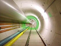
Laying the single 700-mm gas pipeline in the 3-m wide shield tunnel (Fig. 2) is the next phase of construction, with pipeline operations between Futtsu and Higashi-Ogishima to commence in March 2009.
Design pressure of the gas line is 6.67 MPa.
Shield tunneling
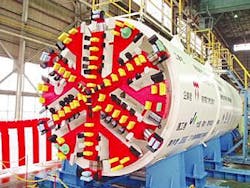
Shield tunnel boring uses a steel cylinder called a shield machine to dig a tunnel through the soil (Fig. 3). Every 1.2-1.5 m a concrete segment is fabricated inside the shield machine to prevent the wall from collapsing and to stabilize the tunnel shaft.
In addition to the record single-machine length achieved on this project, pre-use endurance studies of the shield machine allowed the work to be concluded without replacing any parts, including the cutter bit.
A cutter head is mounted on the tip of the shield machine and rotates to dig through the soil. The claw mounted on the cutter head that does the actual digging is the cutter bit (Fig. 4). The cutter bit is made of cemented carbide, which wears down with digging, so that the exact composition of the bit used must be carefully chosen according to soil type.
The use of one-pass boltless joint segments with a short assembly time allowed major problems to be avoided and a tunneling speed of more than 500 m/month to be maintained.
The one-pass boltless joint segment reduces segment assembly time by making it possible to connect segments by simply inserting a pin. Prior segment construction methods incurred delays by requiring that each segment be bolted into place instead, a lengthier process than pin insertion.
Direct docking
Direct docking the shield machines under Tokyo Bay also dramatically shortened the work period, allowing tunneling to take place from both ends at once.
Direct docking mechanically aligns the shield machines during digging of a tunnel so as to reduce soil intrusion. Fig. 5a shows the shield machines as they approach from opposite ends of the tunnel and prepare for docking. Fig. 5b shows the shield machines after their cutter heads have been mated, connecting the units before their removal. Water cutoff seals keep water out of any remaining unprotected parts of the joints. No additional work is needed, reducing costs and the construction period.
Precision tunnel shaft surveying and horizontal bore probing from as close as 50 m made it possible to achieve millimeter precision in bringing the shield machines into alignment with one another.
The machines docked at a water pressure of 0.6 MPa. ✦


