Simulation examines ice, hydrate formation in Iran separator centers
A simulation with Pipephase and Hysys software showed that polyurethane insulation with thermal conductivity of 0.22 w/m-°C. and an electric heater could solve the problem of ice and hydrate formation in two separator centers in Iran.
Ambient temperature and wind velocity affect the formation of hydrates in the KA and NA separation centers. The centers are in southwest Iran near the city of Bushehr. The area has seven separation centers that remove condensate from the gas stream. The NA region has three centers, while the KA region has four.
The hydrates and ice form during cold weather and interfere with operations of the centers, especially those at a higher elevation, such as Centers NA-2 and KA-1.
At low ambient temperature, ice and hydrates form in areas that experience large pressure decreases or where the heat transfer duration between the fluid and the surroundings increases because of slow fluid flow.
Most of these problems concern the fuel supply system and also the liquid-level instruments on the first-stage separators.
In the fuel supply system, the gas pressure decreases from 80 to 4 bars across a control valve. This pressure drop lowers the gas temperature after the control valve to below the hydrate formation temperature, causing hydrates that either plug or restrict the gas flow.
In the future, gas production in the NA and KA fields will decrease, which also will decrease the inlet feed temperature to all centers.
This study included the installation of a 20-kw electric heater to increase the inlet feed temperature.
Gas hydrates
Gas hydrates are crystalline, non-stoichiometric, clathrate compounds. They form when the gas contacts water under favorable temperature and pressure conditions. Gases that can form hydrates include natural gas compounds such as CH4, C2H6, C3H8, iC4H10, CO2, and H2S. Also N2, O2, noble gases, and hydrocarbons such as cyclopropane can form hydrates.
The water molecules in the hydrates form a cage-like crystal structure through hydrogen bonding around the entrapped gas molecules. The gas hydrate structures are designated as Type I, Type II, or the recently determined Type H.1 2
Type I and II have two types of cavities and structures, while Type H has three types of cavities. Various sources provide extensive information on gas hydrates.3-5
Preventing hydrates
In general, hydrate prevention involves at least one of the following:
• Change the process operating conditions so that hydrate does not form, such as by adjusting temperature and pressure.
• Eliminate water from the gas flow to prevent the formation of free water.
• Use inhibitors.
Three methods for adjusting the process temperature and pressure are:
1. Install insulation to maintain the temperature above the hydrate-formation temperature.
2. Install heaters such as electric or gas heaters, jacketing, and electrical tracing to increase the process temperature above the hydrate formation zone.
3. Decrease the process pressure that can cause the temperature to decrease below the hydrate-formation temperature.
The process can eliminate water in two ways: absorption and adsorption. Common commercial adsorbents include:6
• Silica gel.
• Silica-based beads.
• Activated alumina
• Alumina-gel ball.
• Activated bauxite.
• Molecular sieves.
All adsorbents work in the same way except for the molecular sieves that typically require a higher regeneration temperature. Operators use these adsorbents when the process requires more than an 80° F. dewpoint decrease.
Large gas volumes at high pressures usually require the absorption process. The process usually includes triethylene glycol (TEG) or diethylene glycol (DEG) to remove the water from the gas. This method provides a 40-50° F. dewpoint decrease.
Inhibitors also can decrease the hydrate-formation temperature.6 Common inhibitors include ethylene glycol, TEG, and methanol. In cold weather, glycol viscosity causes difficulties; and therefore operators often prefer methanol.
Ethylene glycol and TEG require regeneration units but methanol does not.
Separation centers
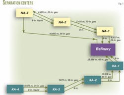
The NA reservoir has three gas gathering and separation centers (Fig. 1). Centers 1, 2, and 3 receive gas from 7, 7, and 8 wells, respectively.

The NA reservoir has an estimated 16.511 tcf of original gas in place. Each well produces about 65-75 MMscfd to an individual two-phase gas and liquid separator at the three centers. An automated valve on the inlet line of each separator controls the pressure and flow rate with prespecified commands.
The separated gas goes directly to a gas pipeline while the separated liquid enters a three-phase separator. The condensate removed in the three-phase separator goes to a refinery.
The KA reservoir has four gathering and separation centers. Centers No. 1, 2, 3, and 4 receive gas from 10, 6, 7, and 6 wells, respectively. The surface facilities and controls at both the KA and NA centers are the same.
The KA reservoir has an estimated 19.4 tcf of original gas in place. Each well produces about 75-90 MMcfd.

Fig. 2 illustrates the gathering and separation process.
Fuel-gas systems
Both the NA and KA separation centers have experienced problems with hydrates and ice forming in the fuel-gas line and the control valve.
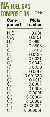
The second-stage separator supplies the fuel gas through a 50 m, 2-in. line. Tables 1 and 2 list the gas composition.

The pressure-control valve reduces the fuel-gas pressure to 4 bar from 80 bar.
Tables 3 and 4 indicate that if the valve’s input temperature decreases below 37° C., then the outlet valve’s temperature due to the pressure drop decreases to less than -1° C. Ice, therefore, will form.
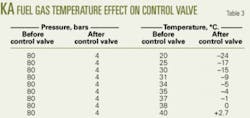
Calculations indicate that hydrates will form at -4° C. at a 4-bar pressure.
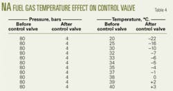
Both the NA and KA centers will have similar problems, assuming the same fuel-gas temperature and pressure at both.
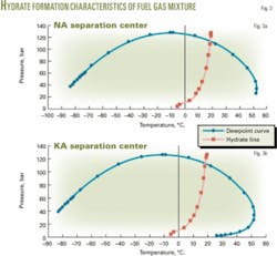
Fig. 3 shows the Hysys simulation results.
Line without insulation
Pipephase software simulated the conditions of the 2-in. pipeline with the existing gas specifications and in winter conditions. These calculations included a minimum 0° C. air temperature and maximum 20 m/sec wind velocity, although local reports indicated a minimum 1° C. temperature and maximum 15 m/sec velocity. A lower temperature and increased wind velocity will intensify the hydrate problems.
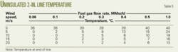
Table 5 shows the results of the simulation.
Because the hydrate temperature at 80 bar is 15° C., as calculated by Hysys, it is likely that hydrates may form in front of the pressure control valve.
The simulation assumed a negligible pressure drop in the 50-m line and a temperature of 40° C. at the start of the line with a 0° C. ambient temperature.
Insulation, heater
Pipephase software simulated the effects of using polyurethane insulation around the 2-in. line, with a thermal conductivity of 0.018-0.022 w/m-°C. and 50-mm thickness. The calculations assumed a 0° C. ambient temperature and 20 m/sec wind velocity.
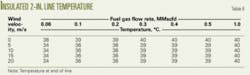
Table 6 presents the results.
Because well production will decrease in the future, the calculations assumed the process would include a 20-kw heater to maintain the separator’s feed temperature. Parameters in the calculations included a 0.5-MMscfd fuel-gas flow, 50% heater efficiency, and a 30° C. temperature difference across the heater.
Minimum gas temperature at the well separator’s inlet is 40° C., which is much greater than the hydrate-formation temperature.

Hysys calculations show that hydrates form at about 15° C. for the produced gas composition at NA and KA separation centers. In normal operations, therefore, hydrates are not a problem for the flowing fluids even during the coldest day. But hydrates do affect the stagnant liquid in the high and low-liquid-level switches, level transmitters, and level indicators on the first-stage separator at each center.
When the liquid level in the separator is high, the float that is sensing the level will send an operating message to the output control valve. If the liquid freezes, the float cannot move and the control valve remains open until all liquid drains.
The condensate will then flow out of the separator with the gas.
Likewise, the low-liquid-level switches also will freeze at the same time and the instruments will transmit the wrong nonproportional liquid level causing a carry-through problem. Carry-through problems in the first-stage separator will affect operations of the second-stage separator.
Carry-over problems also may occur if the liquid level in the separator is low. In this case, the float sensing the level will send a message to limit outgoing liquid flow or to close completely the outlet control valve at the first-stage separator.
If freezing occurs, the liquid level will increase and gas condensate will overflow the separator. This carry-over problem causes difficulties in operation of the second and third-stage separators.
Time calculations
Equations 1 or 2 (see equation box) provide an estimate of the time required for ice and hydrate formation, while Equation 3 calculates the convectional heat transfer coefficient.
For Reynolds numbers between 40,000 and 400,000, the values of C and n in Equation 3 are 0.0266 and 0.805, respectively.
Polyurethane insulation, with a 0.02 w/m-°C. thermal conductivity, is good at maintaining the temperature. To determine the time required for the temperature to reach the hydrate and ice formation limit, a designer can use Equation 4.
With polyurethane insulation this equation indicates that in the instrument leg and a 5 m/sec wind velocity, the times are 30 hr to form ice and 90 hr to form hydrates.
If the wind velocity increases to the 20 m/sec maximum condition, then ice would form in 10 hr and hydrates would form in 30 hr.
Glycol injection
The reasons for not using a glycol injection system in KA or NA separation centers are as follows:
• The refinery lacks a glycol-regeneration system. Such a system would cost about $600,000, based on the 2000 gas throughput of 8,400 kg/hr.
• Need to invest about $320,000 for two 200-hp glycol pumps to pump glycol from the refinery to the NA center.
• High cost of transporting about 200 cu m/day glycol with 10 trucks from the refinery to KA.
• Maintenance, operating, and spare parts costs for all pumps in the NA and KA separation centers.
• Potential of the glycol injection system and regeneration unit to pollute the environment.
• Requirement for about 530 tons of makeup glycol, costing more than $30,000 for 5 months/year.
• Less cost for the insulation and electrical heater than for a glycol injection system.
Acknowledgment
The author is grateful to the Shiraz University for supporting this research. ✦
References
1. Gas Processing Suppliers Association (GPSA), Engineering Data Book, Vol. II, 1994, pp. 20.1-20.43.
2. Englezos, P., “Clathrate Hydrates,” Industrial and Engineering Chemistry Research, Vol. 32, 1993, p. 1,253.
3. Sloan, E.D., Jr., Clathrate Hydrate of Natural Gases, New York, Marcel Dekker Inc., 1990.
4. Sloan, E.D., Jr., “Natural Gas Hydrate,” JPT, Vol. 43, 1991, p. 1,414.
5. Sloan, E.D., Jr., Happel, J., and Hanto, M.A., Natural Gas Hydrates, New York, Academy of Science, 1994.
6. Kohl, A.L., and Riesenfeld, F.C., Gas Purification, Houston, Gulf Publishing Co., 1985.
The author

Feridun Esmaeilzadeh (esmaeil @shirazu.ac.ir) is an assistant professor at Shiraz University, Shiraz, Iran. His primary research interests are related to gas-condensate reservoirs, supercritical fluids, phase equilibrium (EOS), simulation, and surface facility problems. He previously was with the National Iranian Oil Co. Esmaeilzadeh has a BS in chemical engineering from Abadan Institute of Technology, an MS in chemical engineering from Shiraz University, and a PhD in chemical engineering from Sharif University of Technology.