Tools, procedures facilitate complex well completions
A new array of downhole tools and completion methods provides a way for the industry remotely to gather data and control fluid flow from the complex downhole environments frequently encountered in today's well completions.
Most of these tools and applications require a customized design to account for differences in produced fluids, reservoir properties, well geometries, and geographic locations.
A sampling of some recent tools and applications include:
- Cableless telemetry that uses a well's tubulars to transmit downhole data to surface.
- A formation testing tool run while drilling to measure formation pore pressure and provide pressure drawdown measurements that are useful for designing the well completion as well as for managing the borehole fluids during drilling.
- A combination of gravel-packing service tools and oil-based compatible fluids to reduce gravel-pack completion risks in openhole pay intervals with exposed unstable shales.
- Continued development of intelligent completion hardware that provides more reliability and functionality in diverse well geometries and complex reservoirs.
Cableless telemetry
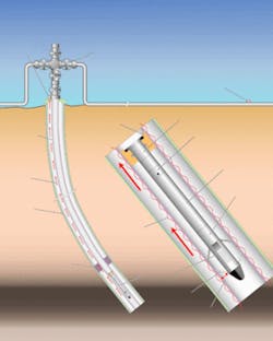
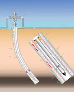
The Expro Group last year acquired a cableless telemetry technology (CaTS) that allows recovery of real-time information from downhole sensors that use existing steel tubulars in a well to carry the signals from downhole sensors. The system works without dedicated cables or instrument lines in the wells.
According to Dean Brown, data services manager for Expro, the technology relies on algorithms, originally developed by Flight Refueling Ltd. in the UK during the last 10 years, for processing the downhole signals.
Flight Refueling and Shell Nigeria ran the first field trial of the system in March 2003 in a well in Nigeria.
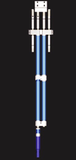
Expro describes the standard system (Fig. 1) as having a resonating quartz pressure and temperature transducer, but future versions of the system also will include valve-position sensors, flow sensors, and sand-production sensors.
Brown said one application for the system is to monitor reservoir pressure using abandoned wellbores. In July 2004 Shell installed nine such gauges in a well in Wyoming that had bridge plugs isolating each zone in an approved plug and abandonment procedure. Expro expects this installation to transmit data for about 3 years. In upcoming applications, Expro will be installing up to 20 gauges/ well.
Brown explained that, for most long-term monitoring applications, operators will want about one or two readings/day. In multiple gauge installations, the data header sent by the sensor serves as an address to identify the source of the signal.
Expro indicates that the system allows for two-way communication, uses various sensor types, eliminates the need for completion equipment penetrations, and lowers installation costs because there is no need for a dedicated cabling system for long-term well monitoring. Extra costs in a system with cables include such items as clamps, extra rig time to run the cables, and the addition of penetrations in the wellhead, packers, hangers, or x-mas tree to allow the cable to pass through this equipment.
In many cases, wireline-conveyed equipment can retrieve the gauges in the event of failure.
The system transmits data packages at extremely low frequencies (ELF) through the steel tubulars to either a station at the wellhead or to a remote gathering station. In the Nigeria test, the data traveled up the casing to surface and then along the flowline to a gathering station 5 km away, according to Brown.
The system does have depth limitations and the number of total data packages that the tools can send decreases as well depth increases. Expro says the tools from about 8,500 ft can transmit a total of about 3,000 data packages during their lives, while this number can decrease to fewer than 500 when the tools are at about 11,500 ft, subject to well parameters.
Expro indicates other applications for the system include monitoring reservoir pressure with gauges mounted outside the casing and from below beam pumps.
System specifications include about a 12,000-ft transmission range depending on well configuration, 257° F. maximum operating temperature, a 32-ft tool length with the standard battery pack, a 2.5-in. tool OD, and a standard lithium battery.
Formation testing while drilling
A new type of formation tester used during drilling eliminates the rig time required to run wireline tools, especially in deviated wells, according to Baker Hughes Inteq. Matthias Meister, project manager for Inteq, described the formation tester's performance when used in three deviated Norsk Hydro AS wells in the Troll field off Norway.1 The tool, Inteq's TesTrak, measures pore pressures during brief drilling pauses.
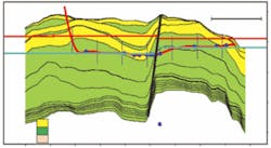
Meister said that for eight bit runs and 235 rotational hr, the tool acquired 231 pressure points at 89 stations over a drilling distance of 10,780 ft. The wells had inclinations from 50° to 90°. He explained that post-well analyses of the pressure data added confidence to the real-time data acquired during drilling and that the tool's memory data supported the real-time pressure measurements. Fig. 2 shows the test points in one of the wells.
Besides characterizing the reservoir from the formation-pressure drawdowns, the pressure information also provided data for managing the mud weight and equivalent circulating density.
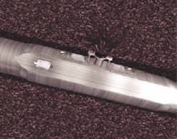
The tool uses a pad-sealing element, similar to the current generation of wireline tools, to seal off a portion of the borehole wall and establish pressure communication with the reservoir (Fig. 3). An intelligent pump-control system operates the tool downhole in a closed-loop control with the integrated formation rate analysis (FRA) and allows for different types of tests.
Besides obtaining a basic test with a single drawdown, the tool also provides optimized tests with repeated drawdown and buildup tests without reseating the pad. Meister indicated that this feature allows in situ verification of formation pressure measurements.
The formation-pressure test consists of multiple drawdowns in a sequence. Meister said that the multiple repeat tests automatically adjust to the formation condition, which leads to an increased accuracy as well as confidence in the measured pressure and mobility data while at the same time allowing to compare the results under much different drawdown parameters in real time.
The tool allows for the use of different drawdown rates during the repeat tests based on downhole analysis. Meister explained that the downhole intelligent control system analyzes each pressure test data set with the FRA algorithm and adjusts the drawdown rate, volume, and buildup duration based on the FRA quality indicator, formation mobility, and buildup criteria. Repeat tests confirm the results and the test will terminate early if it meets the preselected buildup criteria, thus minimizing the test duration.
Meister said a typical test was done after a stand of drill pipe was drilled down and that the test for three drawdowns lasted about 15 min at one station, including positioning and activating the tool, testing the formation as well as uplinking and decoding the data. The drillstring was stationary for about 4 min, according to Meister. Drilling fluid circulation is maintained throughout the pressure-measurement operation to ensure well safety and provide power to the tool.
Signals from the surface sent with standard mudflow downlink procedures control the tool. Meister explained that each setting could be programmed individually to perform a basic test or a test with optimized test sequences. The downlink allows for the setting of 3, 5, 7, or 10 min maximum test durations.
After the measurement sequence, the tool releases the pad-sealing element from the borehole wall and transmits the measured data to the surface with mud pulse telemetry.
Gravel pack tool
A new gravel pack tool run in conjunction with an oil-based mud compatible fluid can eliminate the need to circulate out nonaqueous fluid (NAF) or oil-based fluid before running a gravel pack. As explained by Hecker in a recent presentation, "Running the screens in NAF significantly increases the probability of successful screen installation and the end result is consistent, cost effective delivery of high rate, low skin completions."2
Hecker explained how ExxonMobil Corp. applied this concept for improving gravel-packed well completions in deep water wells in Block 15 off Angola and in the Hoover and Diana fields in the Gulf of Mexico.
Harvey Fitzpatrick, product manager sand control, for Halliburton Energy Services Group, provided a further explanation on the benefits of such completion practices.
He said conventional gravel-packing practices require the entire cased wellbore and openhole to be displaced from the mud system to filtered brine before running the screens. But managing wellbore stability during this displacement phase has proved to be a challenge, especially when changing from oil-based to filtered brine.
Fitzpatrick explained that running screens in oil-based fluid increases the chance of a successful screen installation into the openhole, but displacing the oil-based fluid from the openhole has caused problems.
Halliburton's solution was to develop its AresPac fluid system that Fitzpatrick said provides a smooth, trouble-free transition from oil-based drill-in fluid to water-based gravel pack fluid. The system enables drilling with oil-based fluid and gravel packing with water-based fluid when an openhole screen is to be placed across a shale zone. The fluid is appropriate in wells with 90-230° F. reservoir temperatures and can be mixed with fresh water, seawater, NaCl, KCl, NaBr, or combinations of salts to meet fluid density and formation compatibility requirements, according to Halliburton.
The following summarizes a generic procedure for running the system in openhole pay intervals with unstable shales.
- Test fluid compatibility to determine acceptable fluid formulations for displacing the oil-based drill-in fluid (OBDIF) with a water-based completion fluid that in the open hole will not cause high viscosity fluid incompatibilities and breakdown the OBDIF wall cake that prevents excessive fluid loss.
- Drill openhole pay section with OBDIF. Condition the OBDIF while drilling using solids control equipment (including sized-shaker screens) to reduce solids size and content while allowing circulation rates sufficient for good circulation and hole cleaning.
While drilling the openhole pay interval, the rig can use a separate set of shale shakers to condition the OBDIF off line of the drilling fluid stream. The shaker screens should be sized to reduce the OBDIF solids size so that they allow the whole conditioned OBDIF to pass through the gravel-pack screen without plugging. This procedure involves using this conditioned OBDIF to displace the openhole gravel-pack interval to save time after drilling the hole to TD and when it is ready for the final displacement, prior to running gravel pack screens.
- Prepare well fluid to run gravel-pack screens. Displace openhole gravel-pack interval with the OBDIF that has been conditioned over the shaker screens sized to the gravel-pack screen gauge size. Tests can determine the shaker-screen mesh needed for conditioning the OBDIF to pass through the gravel-pack screens without plugging. The next step is to clean and displace casing with the conditioned OBDIF. If the well has a riser extending to a subsea blowout preventer stack, the riser also needs to be cleaned and displaced with the conditioned OBDIF.
- Make up and run in hole with screens and gravel-pack assembly containing conditioned OBDIF. Position screen on planned depth in openhole pay interval. The OBDIF in the openhole interval reduces the risk that active or unstable shales will intrude into the wellbore and delay or prevent the gravel-pack screens from being placed. The next step is to set and test the packer.
- Displace OBDIF from openhole gravel pack interval. With the service tool in the reversing position, spot surfactant sweep spacer to clean tubulars followed by OBDIF compatible water-based gravel pack fluid (OCGPF) down the workstring and up into the annulus above the packer.
Shift service tool to the circulating position and pump down the annulus to displace the openhole gravel-pack interval with OCGPF. Surfactant sweep and excess OCGPF remains in workstring annulus above the packer. The service tool must allow the circulation of fluids from the annulus down the washpipe inside the screen, out the screen, and up the screen through the openhole annulus to return up the workstring.
- Gravel-pack operations start with the shift tool to the reverse position. Clean lines and workstring with a surfactant sweep spacer. Follow the cleaning stage with an OCGPF spacer stage, a gravel-pack carrier-fluid pad stage and the gravel-pack slurry. Displace pickle fluids and spacers with gravel-pack slurry. Put 20 bbl of OCGPF spacer on the backside in the annulus above the packer with tool in reverse position. Shift the tool to the circulating position and start gravel packing, taking returns to surface. Pump gravel-pack slurry and displace with completion fluid.
After completion of the gravel pack, the procedure is to shift the service tool to activate the reversing ball check. Pump cleaning sweep stages followed by completion fluid down the casing-by-workstring annulus to reverse out excess gravel slurry. Continue pumping to displace casing full with completion fluid. Then clean and displace riser (if used) to brine, and afterwards actuate and test downhole mechanical fluid-loss control and well control device. At this stage, the gravel-pack service tool string is pulled from the well.
Fig. 4 shows the operational sequence for the procedure.
Intelligent completions
The industry has had available various levels of intelligent completions for several years but the numbers installed have not been great. This is changing. For instance, Donald Ross, intelligent completion manager for Schlumberger Oilfield Services' reservoir monitoring and control group, said that industry's adoption of this technology has crossed a chasm because the adoption rate for the last couple of years has seen a fourfold increase.
He notes high offshore costs for intervention in wells as still one of the main drivers for implementing the technology but the economics for land applications of remote downhole control also have improved for such applications as flow control in injection wells and in multilateral and extended-reach completions.
He said that what is new with intelligent completions is true integration from the wellhead to the reservoir.
The use of more fiber optics has increased. Ross said fiber optics bring a new angle to production diagnostics and allows operators to make intelligent decisions on how to operate wells. In one of Schlumberger's versions of the technology, the fiber allows distributed temperature measurements to be recovered from multiple pay zones and from behind casing or sand screens for such uses as production allocation.
To date, Schlumberger has installed fiber-optic lines behind sand screens in four sand face completions.
Ross said another use for fiber optics is to diagnose the nodal temperature in deepwater risers to control chemical injection treatments to minimize hydrate formation in flow assurance applications.
Pressure and temperature are still the most common sensors but flow also can be measured. Schlumberger's newest downhole flowmeter measures pressure changes with a venturi and density with a gamma-ray densitometer (Fig. 5). The meter also mixes fluid to eliminate the effects caused by well deviations. Ross said Schlumberger installed the meter for the first time in a North Sea well 2 years ago.
Ross explained that one recent innovative use of intelligent completions was in a mature field in the North Sea. In this well, the original borehole had watered out and the operator recompleted the well with two sidetracks. Because the seabed infrastructure was about 8 years old, it could only accommodate one downhole hydraulic control line.
The intelligent completion in this brownfield application used multidrop, multichoke valves on one single hydraulic control line to provide selective production control to each lateral with choking capability. The operator can choke production on each lateral to balance the pressure from each lateral in order to produce the zones commingled.
Ross said this is unique because flow from both laterals is controlled from one hydraulic control line. In this case, production from the lower zone flows up the tubing, while production from the other leg flows outside of the tubing in the annulus before going through the choke and commingling with the flow from the lower zone. This completion allows the operator to minimize gas production from above and water production from below.
The completion has a multilateral TAML Level 5 mechanical and hydraulic seal to prevent any cross flow into the lower section and remove junction collapse concerns.
Electric control valves are another option for the industry. Schlumberger expects to install a five-zone electric completion in the North Sea this year. Ross said some drivers for electric intelligent completions are that the technology only requires one penetration through the wellhead and it allows for infinite downhole choke settings across each of the isolated pay zones. He estimated that currently only about five true electric intelligent completions have been installed worldwide. He said Schlumberger installed its first in 2001 in Indiana in a joint venture to test this technology. The system still works today and the valves have been actuated more than 1,500 times to demonstrate worldwide real-time connectivity of the system, according to Ross.
Schlumberger also has designed an all-digital system that it plans to install in the field this year (Fig. 6). Ross said a digital system avoids piecemeal integration and uses a telemetry system with a twisted pair of cables that allow split loads. This accommodates the different loads needed by downhole components. For instance most sensors require 5 w, while flow valves require 300 w of power. Ross also added that digital systems eliminate noise in power transmission and provide modularity.
References
1. Meister, M., et al., "Pressure Gradient Testing With A New Formation Pressure Testing During Drilling Tool," Paper No. SPE 90425, SPE Annual Technical Conference and Exhibition, Houston, Sept. 26-29, 2004.
2. Hecker, M.T., et al., "Reducing Well Cost by Gravel Packing in Nonaqueous Fluid," Paper No. SPE 90758, SPE Annual Technical Conference and Exhibition, Houston, Sept. 26-29, 2004.
