Analyze hydraulics to select an appropriate PDM
PD MOTORS—Conclusion
The mathematical relationship between internal geometry and performance can guide seletction of PDMs. The selection process matches downhole positive displacement motor (PDM) performance with available hydraulic horsepower, expected bit torque, and downhole cleaning requirements.
Part 1 (OGJ, Jan. 24, 2005, p. 41) of this series discussed PDM power performance based on aspects of the internal geometry, such as lobe number, cavity size, and stage length. Available hydraulic horsepower at the drill bit was also discussed. This concluding article explains how to integrate PDMs into drilling rig hydraulics, with several examples illustrating the rationale.
The starting point for this discussion is the available hydraulic horsepower. The power availability curve is independent of PDM type and depends on mud-pump power and system losses. How the available power changes with flow rate through the circulating system is the essence of the following discussions.
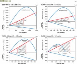
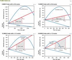
As Fig. 1a shows, a peak exists in available horsepower at a flow rate around 500 gpm, and there is a range of flow rates (400-800 gpm) that is attractive. The best motor for this situation is one that can perform within this flow rate range (400-800 gpm). Other factors that affect the selection of PDMs are:
Torque. Demands from the drill bit work in a particular formation. In general, the higher the number of lobes, the higher the torque capability.
Hole size.The motor must be compatible with the size of drill collars being used.
Flow requirements for hole cleaning. The operating flow rate range must also include this flow rate requirement. Typically, annular return velocities are around 120 fpm. This number is assumed in the following discussion.
Three different drilling situations will be used to illustrate the rationale for selecting a downhole motor: a surface hole 2,000 ft deep; a 12,000-ft hole; and a 20,000-ft hole.
Example 1, surface hole
In the first example, we look at a surface hole drilled to 2,000 ft. The assumptions made for this case are:
Hole diameter = 133/8-in.
Pipe OD = 5-in.
Pipe ID = 4.276-in.
PDM OD1 = 91/2-in.
B, constant2 = 5.11 x 10⁻¹⁰
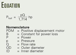
The practical application here is a surface hole in which high torque and flow rate may be important. A 5:6 lobe configuration will illustrate. It is assumed that the motor flow rate range is 500-1,100 gpm. The manufacturer's specified operating pressure (see equation in the box on this page) defines the PDM performance curve.
The difference between the available-horsepower curve and power-consumption curve for the motor represents power remaining for cleaning the drill bit. The final consideration in selecting an operating flow rate is annular velocity. The best flow rate is one that represents a compromise between high mechanical output of the motor, adequate bit cleaning, and adequate annular velocity. Once this flow rate has been chosen, bit nozzles can be sized.
Annular velocity is also plotted in Fig. 1a, showing a 120-fpm requirement. This velocity is plotted to show its restriction on the operating range of the PDM. From inspection it would be necessary to operate this particular PDM in the middle of its flow rate range in order to avoid possible erosion in the hole.
In surface holes, PDMs are often used to give a boost to the bit speed to increase rate of penetration (ROP). More than adequate power is available to operate the PDM. In this case, because few losses exist in the drill system, the PDM is able to operate in the middle of its acceptable range. This observation is supported by the desired annular velocity rate (Fig. 1a). In this case, two mud pumps may have to be used to achieve the desired flow rate.
Example 2, intermediate depth
In the second example, we look at a hole drilled to 12,000 ft. The assumptions made for this case are:
Hole diameter = 95/8-in.
Pipe OD = 5-in.
Pipe ID = 4.276-in.
PDM OD1 = 61/2-in.
B, constant2 = 5.11 x 10⁻¹⁰
Two different motor geometries will be considered for this case: a 5:6 lobe pattern and a 1:2 lobe pattern.
Fig. 1b shows the results calculated for a 5:6 PDM in a 12,000-ft hole. From motor performance data, the torque generated by this motor is in the range of 2,700 ft-lb, which would be available for aggressive drilling; however, the typical torque needed at 12,000 ft is closer to 1,500 ft-lb. The 5:6 motor has more than adequate torque for the operating conditions but operates at lower rotational speeds as compared to a 1:2.1 The full capability of this motor may not be utilized in this case.
Fig. 1c shows the results 1:2 motor under the same operating conditions superimposed. Inspection shows that the motor utilizes more of the hydraulic power than the 5:6 motor. This motor's torque rating is in the 1,900 ft-lb range, and it rotates nearly five times faster than the 5:6 motor. This motor would therefore generate more drilling power at the rock interface and result in a higher rate of penetration. The annular velocity restricts the flow rate to the lower half of the curve, but operating at this flow rate would still allow adequate power to clean the bit.
Example 3, deep hole
Example 3 reviews the case of a deep hole (20,000 ft). The assumptions made for this case are:
Hole diameter = 77/8-in.
PDM OD1 = 43/4-in.
Pipe OD = 41/2-in.
Pipe ID = 33/4-in.
B, constant2 = 1.173 x 10⁻⁹
Note that the value of the constant, B, is about twice as large as the value used in the power consumption curve in the two prior examples.2 This change is motivated by the change in pipe size, mud weight, and hole size necessary for a deep hole.3
Fig. 1d shows the results calculated for a PDM with a 1:2 lobe pattern in a 20,000-ft hole.3 The higher value for B shows that system losses are nearly double in a 20,000-ft hole, compared with using the lower value for B.
There are extreme cases where PDMs are unsuitable. As in this example, in very deep wells there simply may not be enough hydraulic power available for driving a motor. This would come about if all surface pump power were consumed in system losses leaving very little, if any, hydraulic power for a motor.
When available hydraulic horsepower is practically non-existent, bit cleaning has to be accomplished solely by flow. Since drilling rate is relatively low at these greater depths, flow rate is usually adequate for bit cleaning.
It is worthy to note that each of these examples shows only one motor and where it might best be used. Many motor configurations exist. It is possible to find a smaller PDM that has operating conditions within the flow rate limitations as prescribed above.
However, the advantage of using a smaller PDM must be weighed against the annular velocity and required bit cleaning power. In very deep wells, bit cleaning is accomplished by flow and not by jetting. The addition of any PDM to these systems will compromise the overall efficiency of the drilling process.
In any case, a performance analysis and diagram as shown in these examples would show whether a motor could operate successfully in each particular operating situation.
Learnings
PDMs come in a variety of configurations making retrofitting one into drilling operations confusing without proper knowledge of how to evaluate a PDM's performance and properly integrate one into available hydraulics. Critical considerations in selecting PDMs for particular drilling operations are:
- PDM selection requires a complete hydraulic analysis of the on site drilling conditions. The best motor makes optimal use of the available hydraulic horsepower. The flow rate needs to be checked against the annular velocity to make sure it is large enough to provide adequate bit cleaning but not so large that it will erode the wellbore wall.
- PDM performance depends on internal geometry. In general, having a higher number of lobes will generate higher torque at lower output speed. Efficiency usually drops with larger lobe configurations because of friction and fluid slippage.
The processes presented in this article are general and can be applied to any drilling situation and any PDM. Although the equations used in the analyses assume 100% efficiency and no leakage, the results yield valid predictions and analyses of PDM performance in normal operating conditions. Operating a PDM outside of conditions recommended by the manufacturer may cause the bottom hole assembly to stall out and cause detrimental damage. Operating outside recommended limits will also decrease the accuracy of the calculated values.
It is essential to understand the performance possibilities and system limitations in order to truly incorporate the best PDM into an existing drilling system.
References
1. Baker-Hughes INTEQ, "Navi-Drill Motor Handbook," 8th Edition, Baker Hughes Inc., 1998.
2. Schuh, F., "Petroleum Engineer's Equations & Rules-of-Thumb: Drilling Equations," Dallas: Petroleum Engineer Publishing Co., 1977.
3. Moore, P.L., et al., "Drilling Practices Manual," Tulsa: PennWell Books, 1974, p. 259.


