ORMEN LANGE-Conclusion: Environment drives lay techniques, tool development
The extreme conditions in place at Ormen Lange required careful consideration of not only pipelay technique, but also a wide variety of other technological factors. Norsk Hydro ASA participated in and sponsored development of both new analytical tools and improved corrosion fatigue testing data bases. It also undertook technology qualifications on a post-installed direct electrical heating system to address potential future ice plugs.
This conclusion of a two-part series examines each of these efforts in turn.
Part 1 (OGJ, Dec. 5, 2005, p. 62) looked at the geography and overall development plan for Ormen Lange, giving particular attention to the 30-in. multiphase production pipeline system.
Deep water, harsh environment
Pipeline installation in deep water through extreme terrain has been an issue for several years. Pipeline installation contractors’ studies and front-end engineering and design phases have made progress in addressing this issue. Pipelines must be laid in curves at very tight tolerances to limit future seabed intervention work to an acceptable level.
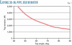
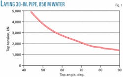
The increase in suspended pipeline length will increase top tension as water depth increases. Increasing the laying top angle relative to the horizontal plane counteracts this effect (Fig. 1). The theoretical minimum is a 90° top angle. This will lead, however, to unacceptable bending moments in the sag bend.
The process of choosing optimum top angle consists of maximizing the top angle while keeping the sag bend moment within acceptable limits in all design conditions. The typical range for top angles for pipelaying in deep waters (>500 m) is 70°-85°.
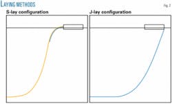
For a conventional pipelay vessel, on which welding of joints into the main line is performed in a close-to-horizontal position, such steep top angles will require a very long stinger to control the transition from near-horizontal to close-to-vertical without imposing excessive stresses in the overbend. One alternative is the J-lay technique, which welds joints into the main line in close to vertical position (Fig. 2).
From a static point of view, the two methods are practically equivalent for the same top angle. Wave-induced vessel motion on the dynamics of the suspended pipeline, however, will create fundamental differences.
The main parameter causing different sensitivity to dynamic effects for the two is the location of the point where pipe leaves the vessel relative to midship. To understand this sensitivity it is useful to study the problem in a two-dimensional vertical plane, defined by the suspended pipeline going through the centerline of the vessel. A combination of the vessel’s surge, heave, and pitch defines the vertical plane motion of an arbitrary point on the lay vessel.
The point of minimum motion is close to midship at the waterline, where there is no effect of the pitch motion on the vertical plane motion. Moving forward, backwards, up, or down from this point increases the effect on the vertical plane motion from pitch proportionally to distance.
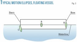
Fig. 3 shows the typical motion ellipses for several locations on a floating vessel:
• Midship at the waterline (A): a vertical ellipse in which the longest axis in vertical direction (heave) dominates over surge.
• Fore at the waterline (B): as (A) but with pitch amplifying the vertical motion.
• Aft at keel level (C): as (B) but with pitch also amplifying the horizontal motion. The phase difference between surge and pitch also causes the ellipse to incline.
A typical J-lay vessel will place large-diameter pipe into the water about 100 m ahead of the center of rotation, assuming that the lay tower is at the bow. This point will be relatively close to the water line, creating the ellipse shown in point (B) of Fig. 3.
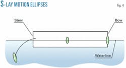
The long stinger required to limit the strains of overbend on an S-lay vessel of the same size will cause the pipe to leave the vessel about 200 m behind and 100 m below the center of rotation, significantly magnifying the vertical plane motion caused by vessel pitch (Fig. 4).
The transverse component will dominate the motion of the stinger tip relative to the pipeline due to the inclination of the motion ellipse. The transverse component will also be critical to stinger tip clearance, while the longitudinal component (in the pipe direction) will be critical in determining the dynamic forces at work in the pipeline.
Wave-induced vessel motions will, as a result, have a greater effect on the S-lay technique than the J-lay technique. The ideal position for a J-lay tower, with regards to favorable vessel motion, will be midship.
These considerations regarding the motion ellipse are fundamental and valid for all floating vessels, whether monohull or semisubmersible. The motion characteristics of individual vessels will, of course, differ with hull geometry and mass distribution. In general, a semisub will have more favorable motion characteristics than a monohull of comparable length and dimension. In certain cases, however, such as long periodic swell (greater than 20 sec), the semisub’s resonant motion would make the monohull more operable.
Analysis tool
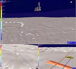
In preparing for Ormen Lange, Norsk Hydro actively participated in and sponsored development of a state-of-the-art tool for analysis of complex pipelaying operations. The development project sought a software tool to simulate the structural response of pipe during laying and allow three-dimensional inspection of the results by graphical visualization of the laid pipe on the seafloor, including pipe details with analysis results (Fig. 5). The resulting simulator, including visualization, is available on desktop computers.
Simulator features important for Ormen Lange are:
• Representation of very large three-dimensional digital terrain models.
• Depiction of the interaction between pipeline and seabed (free spans, stability).
• Simulation of the pipelay process including feeding of elements.
• Laying within tight tolerances.
• Modeling of an arbitrary current profile.
• Modeling of seabed interventions (rock dump or dredges).
• Code check.
Participants in the Ormen Lange project decided that all major marine operations will be modeled on the simulator. Potential applications of the simulator include:
• Engineering.
• Visualization.
• Verification.
• Operational planning.
• Familiarization and training.
The simulation tool will be valuable in assessing the pipelaying operation, especially in areas where the routes are narrow and the seabed geometry complex. The three-dimensional simulator has given Norsk Hydro useful hazard and operability input on several recent projects.
All installation contractors have been offered the tool free-of-charge for unlimited use within the project.
Technology qualification
Technical solutions that are proven, or technology that will require only qualification work to be proven, form the basis of the overall technology development strategy for Ormen Lange. Solutions needing research and development will be avoided.
The project will conduct parallel studies of alternative solutions that may give safety, environmental, economic, or operational advantages. This includes support of research activities as appropriate. The scope and execution of these parallel studies will ensure that the technologies developed can be used in other projects, even if Ormen Lange decides not to use them.
The qualification program for the 30-in. pipelines encompasses:
• Free spans (initiated as research activity).
• Corrosion fatigue.
• Stress vs. cycle (S-N) curves specific for the project.
• Pipelay criteria.
• Deepwater pipeline repair system.
• Large-bore tie-in system.
• Field-joint coating.
• Dredging equipment.
• Direct electrical heating (DEH).
The balance of this article will address two of these qualification activities: corrosion fatigue and DEH.
Corrosion fatigue testing
As discussed in the first part of this series (OGJ, Dec. 5, 2005, p. 62), the Ormen Lange project performed considerable work in establishing revised guidelines for vortex-induced vibration response. The S-N data used in current design codes, however, continue to work well for fairly short free spans on flat seabed.
But the data that form the basis of the existing curves used in the codes date back to the 1970s and contain very little weld information on high-low (eccentricity), defects, and groove geometry.
This is probably why 3-mm high-low is included in the design curves. It is also well documented that eccentricity has a significant influence on fatigue life due to stress concentration factor.
For modern pipeline welding high-low is rarely greater than 2 mm. Automated ultrasonic testing accurately documents high-low and lack of penetration in the root, as well as other planar defects. High-low will therefore only be present across a limited part of the circumference.
The use of steel catenary risers has prompted a major effort in documenting and improving the fatigue performance of welds. This work has resulted in use of the E curve and better, with a limitation of eccentricity of 0.5 mm. This standard, however, is not practical for long pipelines.
It was therefore decided to improve the Ormen Lange databases for S-N curves based on the welding and non-destructive testing methods used and the loads typical for the project. It was particularly important to determine the confidence levels of the data used, as risk-based design is widely used in the project.
The difficult route, waiting-on-weather, and laying down the pipe increased the risk of fatigue damage. Fatigue design in the laying phase with more than the normal 10% of the Miner sum for installation is an important success factor and risk reducer for the installation phase.
The linear damage accumulation rule of Miner’s sum is frequently applied to fatigue test results and is defined:
null
D = SUM (ni/Ni)
null
where D is a quantified damage accumulation parameter, ni is the number of cycles experienced at a maximum stress level, and Ni is the number of constant amplitude cycles to failure at the maximum stress level oi. Typically, failure is taken to occur when D reaches unity.
The 6-in. monoethylene glycol lines and umbilical also need improved fatigue performance during installation and the temporary phase to create a robust risk picture.
Test program
Fatigue stresses from vortex-induced vibration in operation are characterized by high mean stress (~250 MPa) and stress amplitudes of 10-40 MPa. Given acceptable defect sizes in the root, these fatigue stresses result in a range close to threshold, even for the environment inside the pipe.
The absence of relevant tests in this part of the S-N curve requires dedicated experiments. The number of lifetime cycles is on the order of 2 million, making traditional designs based on S-N curves of limited use. Dedicated tests to the design number of cycles will be performed and the resulting final defect sizes will be checked against allowable defect sizes for the static loads present.
Much higher amplitudes and lower mean stress will shape the installation-phase load case. Dedicated S-N curves will create a robust design, leading to the test program shown in the box above.
Preliminary results
Allseas Group SA has made test welds with the procedures qualified for the first 33 km of the pipelines from shore. Maximum 2 mm high-low was used and efforts were made to intentionally create LOP. Half of the welds were done without intentionally making LOP. Despite this, very little LOP was found in the specimens; locally up to about 1 mm, but on most specimens only about 0.5 mm.
The Foundation for Scientific and Industrial Research at the Norwegian Institute of Technology ran tests on 65-mm-wide tensile specimens at a stress range of about 150 MPa to establish scatter data and the effects of the factors discussed earlier. The specimens had a high-low range of 0.5-2 mm and LOP approaching 1 mm. Initial data fall mostly above the mean E curve, including the effect of high-low.
Electrical heating system
Ormen Lange plans to use continuous MEG injection during production to prevent hydrates and ice forming in the deepwater sections of the 30-in. line. The primary hydrate-remediation method is depressurization. The secondary hydrate and ice remediation method is pipeline replacement. Pipeline replacement is very expensive, leading to alternatives for addressing ice plugs.
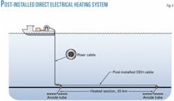
Ormen Lange’s stakeholders decided to qualify a post-installation direct electrical heating system (Fig. 6) before 2007 start-up and to evaluate the need for fabrication and storage of long-leadtime items. Fabrication, hiring of the necessary equipment, and installation of the direct electrical heating system would take place if ice plugs occur.
Melting ice plugs requires a temperature increase of 3° C., which the 8-mm polypropylene insulation used will allow. Only the direct electrical connectors for attaching the post-installed heating cable will need to be put in place during the 2006 pipelay. A vessel equipped with electrical power generators will operate the direct electrical heating system. The vessel will install the electrical heating cable close to the affected pipeline and supply current through the heating cable to each of the pipeline connectors, spaced about 20 km apart.
Any need for ordering long-lead items will be established during the qualification work to have a fully-qualified direct electrical heating system ready by the start of production in 2007.
Acknowledgments
The authors acknowledge the contributions of the Foundation for Scientific and Industrial Research at the Norwegian Institute of Technology, the Norwegian Marine Technology Research Institute, Reinertsen Engineering AS, Allseas, Saipem SpA, Statoil ASA, and the Norsk Hydro Research Center. ✦
Corrosion fatigue test program
The unusually long free spans used for Ormen Lange required extra rigor in fatigue testing. Stress vs. cycle (S-N) curves for welds and crack growth tests using large compact tension (CT) samples received particular attention.
The S-N test program looked at curves for welds with varying high-low and lack of penetration (LOP) from installation contractors in two contexts:
• Segment tests were performed in open air at about 150 MPa to establish scatter and the effects of high-low and LOP.
• Chained segment tests were performed in both open air and seawater environments with the stress amplitude distribution of a typical free span.
The crack-growth tests used a variety of internal environments in both open air and seawater settings. Internal environments assessed were:
• Formation water, partly pH stabilized with inhibitor (the worst-case scenario for the bottom of the pipeline).
• Condensed water, pH stabilized (the actual case for the bottom of the pipeline).
• Condensed water, saturated with iron (the worst case for corrosion of the top 90% of the pipeline circumference).
Crack growth tests were also performed on welding and other hazard areas and on the parent plate material.
