North Sea Pipelines- Conclusion: Dual-diameter pigging reaches new extremes; Langeled looms
Statoil has extensive experience in both dual-diameter pigging of subsea pipelines and the environmental ramifications of pipeline commissioning. This second article in a two-part series discusses pig design for dual-diameter systems and the environmental aspects of commissioning operations, presenting relevant field experience.
This concluding article also elaborates on Statoil’s commissioning concept for the 1,200-km Langeled project from Norway to the UK, scheduled for commissioning in 2006-07.
The first part of the series (OGJ, Nov. 21, 2005, p. 66) discussed commissioning concepts for single and multidiameter pipelines; air drying of internally coated, export-gas-quality pipelines; and dewatering of pipelines with hydrocarbon gas.
Dual-diameter pigs
Statoil’s experience in dual-diameter pigging from previous pipeline projects includes diameters ranging from 6 to 36-in. The technology allows existing J-tubes and risers to be used rather than installing new, more expensive ones.
It is essential that the line can be pigged in order to ensure the safe and efficient working of the pipeline and to facilitate commissioning. Dual-diameter pigs have been in use for some time and those designed for changes of between 2 and 4 in. in smaller pipe diameters are now part of most manufacturers’ standard range.
Not many pigs have been designed, however, for larger diameter differences, and still fewer can provide a good seal in both diameters. In fact, intermediate pigging traps typically have been used when large step sizes are involved and a good seal required.
The Åsgard transport pipeline presented a huge pigging challenge with its 28-in. and 42-in. diameters. During precommissioning and commissioning of the pipeline, pigs were run the opposite direction-from the landfall site-in order to perform flooding, cleaning, electronic gauging, and dewatering of the line. Pigs capable of performing their tasks in both 42-in. and 28-in. pipe, the largest known change in diameter for an operational pig, had to be developed.
Water depth excluded a conventional 42-in. steel riser. Production was therefore achieved with a number of 14-in. flexible risers connected to a subsea export riser base (ERB).
Statoil initially evaluated a conventional 42-in. subsea launching facility against a reduced-diameter concept. A 42-in. launcher would have enabled the use of conventional single-diameter pigs, but at a high cost and high risk to the subsea structure. A 28-in. subsea launcher was eventually selected, which required specially designed 28-42-in. pigs.
The 28-in. ERB is connected to the 42-in. pipeline via a 28-in. expansion spool with mechanical connectors and a 28-42-in. transition piece.
Operational pigs are preloaded into cassettes, lowered to the seabed, and connected to the 28-in. manifold prior to launching through the 28-in. section of line and into the 42-in. pipeline for the 710-km transit to the onshore plant at Kårstø.
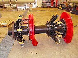
The large diameter ratio prompted the development of a new method of supporting the pig and of minimizing the hoop stress on the seals when entering the smaller diameter pipeline. Fig. 1 shows the prototype pig made of two basic components:
• The wheel suspension unit, capable of supporting and centralizing the pig in the 42-in. pipeline.
• The disc seals, with cockle inducers, for allowing the 42-in. seals to collapse in a controlled manner in the 28-in. pipeline.
A set of conventional sleeper discs was also added behind the main seals to improve sealing efficiency.
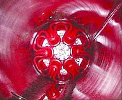
Fig. 2 shows the collapsed discs in the 28-in. pipe section.
The suspension modules consist of eight suspension arms, each linked to a central shaft so that when one wheel arm is deflected, the other seven are also deflected. The shaft resists the deflection with eight springs. The total spring force in the cylinder is greater than the weight acting on the module. The pig rides along the centerline, restoring force being greater than its weight.
The contribution to pig friction and differential pressure from the wheel module is negligible in both line sizes, being merely rolling friction from the wheels. To avoid overloading the wheels, however, it is important that the force-deflection curve is as flat as possible; i.e., upon the pig’s entering the 28-in. pipeline, the loading on the wheels should not change significantly. This can be achieved by optimizing the linkage geometry.
This pig design was successfully employed during field operations and can also be used for towing inspection vehicles in the future. This concept has also been successfully used in a later project, with a 10-16-in. diameter variation.
A multidiameter tool with the ability to travel through a long, small-bore flexible riser starting at a floating production facility, going down to the seabed, and into a large-diameter pipeline is the ultimate use of this technology, eliminating the need for complex subsea pigging operations. The cost and complexity of such tool development, however, especially for large diameter ratios, currently limit its widespread use. But there are certain applications and new gas-transport concepts that have been made feasible with the new technology.
Environmental aspects
The oil and gas industry faces an increased focus on environmental issues while conducting business. Discharges to air and sea are inevitable during precommissioning and commissioning of pipelines. Large quantities of water are pumped through the pipeline during these operations. This water is normally treated with corrosion inhibiting chemicals to reduce internal corrosion.
Chemicals like methanol or glycol may be used to prevent hydrate formation and will normally be discharged into the sea during commissioning. Flaring or venting large quantities of gas has been accepted practice during pipeline drying for many years.
In order to reduce the environmental impact of these operations, while maintaining corrosion protection, Statoil has been working for several years to:
• Develop concepts and methods that reduce the discharged volumes of treated water.
• Use the most environmentally friendly chemicals available and reduce the quantities used.
• Monitor and identify the effect of discharges on various marine species.
Statoil has developed new concepts and reduced total discharges significantly compared to earlier projects. Satisfactory corrosion protection can be achieved with an oxygen scavenger (sodium bisulphite) and biocide (glutaraldehyde) only.
A new method using the increased pH of seawater has been employed successfully on some projects and will be evaluated for use in future pipelines. This method provides superior corrosion protection and reduces the impact on the ecosystem, but it causes precipitate to form and settle in the pipeline, requiring additional pigging.
Extensive small-scale testing has proven that smaller doses and new types of chemicals can be used on larger projects. Laboratory tests and field monitoring show that the environmental impact of discharges of chemically treated water from pipelines is negligible, providing the right chemicals are used correctly.
The Norwegian State Pollution Control Authority (SFT) has not allowed, until recently, pipeline discharges between mid-May and mid-August due to the typically high level of biological activity during this period.
All testing and field operations, however, have revealed very limited and short-term effects to the marine ecosystem caused by the residues from linefill chemicals. Publicly available data also show that spawning activity during these months is not particularly high in the North Sea.
We thus believe that future discharges of water, correctly treated with chemicals, should be possible without a general seasonal restriction, giving more schedule flexibility to new projects.
Methods for pipeline drying have been optimized, eliminating flaring of large quantities of gas and establishing new paradigms for pipeline commissioning.
Langeled project
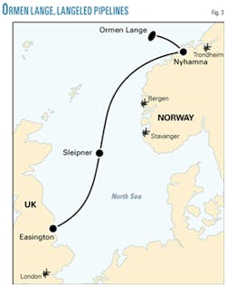
The Langeled gas transportation system will be the world’s largest (1,200 km, 42-44-in.) subsea gas pipeline, bringing gas from the Ormen Lange field to the southern UK (Fig. 3). Ormen Lange is the largest gas field under development on the Norwegian continental shelf. It lies 100 km off the northwest coast of Norway in water 800-1,100 m deep. The field is to come on stream in October 2007.
Operator Norsk Hydro has contracted project execution of Langeled to Statoil, and the project organization is staffed with personnel from both Statoil and Hydro. The partners in Ormen Lange are Hydro (18.0728%, operator for development phase), Royal Dutch Shell PLC (17.0375%, operator for production phase), Petoro AS (36.4750%), Statoil (10.8441%), BP PLC (10.3420%), and ExxonMobil Corp. (7.2286%)
The Langeled pipeline will connect the treatment terminal at Nyhamna in central Norway with Easington in the UK. It consists of the 42-in. Langeled North (LLN) pipeline from Nyhamna to the Sleipner platform complex in the central North Sea and the 44-in. Langeled South (LLS) pipeline from Sleipner to the onshore terminal in Easington.
A subsea 42-in. valve station and two 30-in. branch lines and risers will be connected to the Sleipner riser platform, allowing for import-export to the existing Norwegian gas transportation system.
Langeled can be operated in two modes, normal operation and bypass operation. Pigging will be performed in bypass operation, running 1,200 km from Nyhamna to Easington.
In normal operation, the subsea 42-in. valve is in the closed position, and LLN and LLS are operated as two separate pipelines with different design pressures. In bypass operation the system is operated as one pipeline with three different design pressures. LLN has two design pressures, with a design break 370 km south of Nyhamna. For quality reasons, gas mixing will normally take place at Sleipner before export to the UK. Maximum capacity will be 82 million cu m/day and 74 million cu m/day, for LLN and LLS, respectively.
Installation will occur over the course of two work seasons. LLS will begin operations in October 2006 and LLN 1 year later.
The start-up and lay-down heads will be prepared and loaded with pigs for the initial flooding, cleaning and gauging operation. These heads and pigs will also be part of the wet buckle contingency system during laying.
Commissioning plans for the southern pipeline are conventional and include initial flooding, cleaning and gauging, hydrotesting, dewatering with air, drying with air, nitrogen purging, and gas filling. A temporary pig trap will be included at the subsea valve station at Sleipner. LLS will be operational, transporting sales gas, prior to commencement of RFO operations on the northern pipeline.
Planned commissioning operations on the northern pipeline are far more complicated. The design break requires two separate hydrotest operations. The 627-km pipeline has only one end accessible for pig loading, which will be connected to the already operational southern pipeline.
After flooding, cleaning, gauging, and hydrotesting, the midline tie-in and tie-in to the subsea valve station at Sleipner will be performed. The dewatering train will then be loaded at Nyhamna and propelled to Sleipner with seawater. The Sleipner subsea valve station includes several 2-in. valves downstream of the 30-in. tee to receive and recondition parts of the train.
The train consists of several batches of glycol, some of which will need to be changed out through the 30-in. riser. The water in the riser is changed out with glycol from the train during the same operation.
After the glycol change-out is completed, a 30-in. pig propelled by nitrogen from the platform will pump the riser glycol into the last batch, requiring platform operations and complicated ROV assistance.
After completion of the train reconditioning and final positioning of the train, natural gas will propel the train back to Nyhamna. Sleipner will control pressure of the gas supply. A temporary water flow control valve and flowmeter installed at Nyhamna will provide train speed control.
Upon arrival at Nyhamna, the glycol-and possibly some gas leaking across and into the glycol compartments-will be routed to the permanent slug catcher for further disposal. The pipeline system will be ready for commercial gas deliveries very shortly after completing this commissioning process.✦


