Horizontal laterals complicate well completions, reentry
Arabian Gulf Oil Co.’s (AGOCO) horizontal well programs in various fields in eastern, middle, and western Libyan oil fields have successfully increased initial production rates, although complicating well completions and cleanouts.
For instance, the horizontal wells in the Sarir field will flow naturally without artificial lift and have increased productivity by two to three fold compared with vertical wells. But improper completions and cleanout practices have led to productivity declines in the wells, and current available means of reentry for logging or workovers have proven unsuccessful.
The learning curve for completing these wells has been steep. Drilling time has decreased to 80 days from 110 days and costs have decreased to $4.0 million from $6.5 million at the start of the program.
Well completions
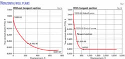
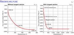
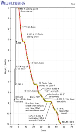
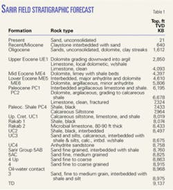
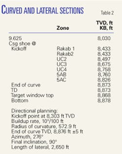
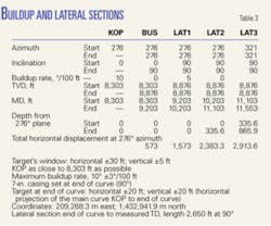
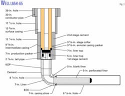
Figs. 1 and 2 as well as Tables 1-3 illustrate AGOCO’s drilling engineering department’s horizontal well. Fig. 3 shows the completion of the first horizontal well drilled.
The first horizontal well drilled included a pilot vertical hole to TD. The procedure involved setting the conductor, surface, and intermediate casing before drilling the vertical hole to TD. The vertical hole was then logged and tested before being plugged back to the planned kickoff point for the horizontal lateral.
The horizontal well plan in Sarir field included:
• Drilling a 26-in. hole to about 120 ft.
• Setting and cementing 20-in. conductor pipe.
• Drilling a 171⁄2-in. hole to about 3,200 ft.
• Setting and cementing 133⁄8-in. casing.
• Welding on the 133⁄8-in. casing a 135⁄8-in., 3,000-psi casinghead for mounting 135⁄8-in. blowout preventers.
• Drilling a 121⁄4-in. hole to about 8,200-ft.
• Setting and cementing in two stages 95⁄8-in. casing.
• Installing a 135⁄8-in. by 11-in., 3,000-psi casing spool.
• Drilling an 81⁄2-in. vertical pilot hole through the reservoir before logging the hole and testing it if necessary.
• Plugging back into the 95⁄8-in. casing to the kickoff depth.
• Kicking off the build section with an 81⁄2-in. bit while controlling the course and the buildup rate until the end of the curved section.
• Setting and cementing a 7-in. liner at the end of curve.
• Drilling the lateral section with a 6-in. or 61⁄8-in. bit to TD.
• Setting either a 5-in. perforated liner to TD or halfway in the lateral, leaving the remainder of the lateral as an openhole completion.
The program included the use of water-based mud to the 95⁄8-in. casing seat and in the vertical pilot hole, before a switch to oil-based mud just before kicking off the lateral to TD.
The well completion included a 7-in. production packer with a 27⁄8-in. tail pipe fitted with a perforated joint and R or F nipples run on a 31⁄2-in. tubing string fitted with a side-door sliding sleeve (SDSS) placed a few joints above the packer.
The program called for landing the tubing as the packer is set, so that the tail pipe enters the 5-in. liner. Wireline operations opened the SDSS to allow placement of an inhibited packer fluid in the 31⁄2-in. by 95⁄8-in. annulus. The SDSS was closed after placement of the packer fluid.
In the next step of the completion, a coiled-tubing unit ran a jetting device to the end of the curved section. The well then was displaced with diesel and coiled tubing was run at a controlled speed to TD. The lateral section then was displaced with a diesel plus additives and nitrogen.
After the coiled tubing was pulled to the end of the curve, the program called for pumping nitrogen until the well started to produce.
Testing of the well included the installation of a separator at the well and flowing the well until production stabilized.
If the production was less than 2,000 b/d, the plan was to kill the well and change the completion to include an electric submersible pump (ESP), sized on the testing results. The ESP completion was run on a 31⁄2-in. tubing string and produced at higher rates.
Horizontal well examples
The first horizontal well in the Sarir field proved to be both a challenge and a success. The L65H-65 (Fig. 3) was the longest horizontal well in Libya with an 11,810-ft measured TD. The main complication in completing the well was that the vertical pilot hole did not encounter hydrocarbons. This required drilling horizontally along the reservoir contour line until drill cuttings contained oil shows.
The well was completed as a semi-barefoot completion with the end of lateral left open and a 5-in. perforated liner installed in the first part of the lateral.
After the cleanup, the well flowed naturally at 3,700 bo/d and 200 Mscfd of gas. The coiled tubing, however, became stuck during the production testing. This problem required the pumping of diesel and Pipe Free spotting fluid to release the tubing.
The Sarir field has many other horizontal wells but in these the vertical pilot hole was eliminated and the learning curve improved significantly.
Well C320H-65 (end of curve at 9,111 ft and measured TD at 11,565 ft), for example, was drilled in 79 days at a cost of $5 million (Fig. 3).
Problems, solutions
AGOCO’s many attempts to reenter most of the horizontal wells drilled to date in the Sarir field with coiled tubing have failed. Either, the coiled tubing would stop in the curved section, or the tubing entered the horizontal section and became stuck. In one well, the coiled tubing parted.
An analysis of the histories of these wells identified various causes for the problems and made recommendations for improving horizontal drilling, completion, and clean-out operations for facilitating reentry into the wells.
One problem identified was that medium capacity rigs had drilled most of the Sarir horizontal wells. These rigs had outdated or unsuitable equipment. Their mud pumps would not deliver enough circulating rate and pressure for the downhole motor or for the measurement-while-drilling (MWD) system.
The rigs did not have top drives and the mud system was unsuitable for good solids removal. The rigs experienced excessive repair and downtime and frequent shut downs in the middle of crucial operations.
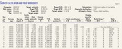
The MWD system for real-time reading had outmoded technology. It provided an azimuth inclination and gamma ray reading (Table 4), but a resistivity tool and current MWD technology would have provided better geologic control.
The vertical pilot hole cost time and money and was unnecessary because the horizontal wells were infill development wells surrounded by vertical wells. Moreover, the water-based mud for drilling the pilot and the plug-back cementing operations may have allowed fluids to react with the shale below the 95⁄8-in. casing shoe. The cementing operation and water-based spacers did not include additives for controlling fluid loss.
The activated shale made kicking off the lateral difficult. In the newer wells, the drilling and completion program, therefore, eliminated the vertical pilot hole.
When used, the cement should be treated with fluid-loss control additives. Also the cement spacers should include calcium chloride or potassium chloride to minimize activation of shales, particularly when drilling the vertical pilot holes with water-based mud.
Without additives, the fluid-loss invasion into the shale was too deep, leading to problems in kicking off the laterals.
The wells required a kickoff point as close to the 95⁄8-in. casing shoe as possible, so that the point at the end of curve was such that it allowed reaching the target depth of the lateral with a buildup rate that was not more than 10°/100 ft.
The oil-based mud was one of the more controversial aspects of the program because it added considerable time to the drilling operation. The mud was switched from water-based to oil-based after the 95⁄8-in. casing was set but prior to the kick off of the lateral. The switch in the mud required about 7 days to dump the water-based mud and mix and condition the oil-based mud.
The operation involved hauling the oil-based mud from previous horizontal wells in tanker trucks to the new wells. This mud transfer required dedicated labor, transfer pumps, and tanker trucks.
In some instances, the mud from the old location was stored in open tanks for an extensive time, subjecting it to weathering (heat, vaporization, rain, and sand storm). This mud, therefore, required additional treatment and conditioning. Additional treatment also was required because the used oil-based mud contained solids and redrilled cuttings from the previous wells.
This hauling and conditioning consumed more time and money than preparing a new batch of oil-based mud. Additionally, the oil-based mud forms a stable emulsion; hence, any change in its oil-water ratio may result in a catastrophic drop out of solids that could plug downhole equipment or stick the bottomhole assembly.
The Sarir reservoir cannot sustain a fluid column with a gradient greater then 0.37 psi/ft; therefore, prior to the drilling of the 7-in. liner shoe (normally above or at the end of curve), the operation involved the use of solid removal equipment and treatments to change the oil-based mud weight to 7.5 ppg from an initial 9.2 ppg. This required both additional time and materials.
Another problem was the circulation pressure in the 61⁄8-in. hole. This pressure could induce fluid loss into the reservoir. Also a high drilling rate of penetration (ROP) would load the mud system with cuttings, increasing its weight and squeezing the oil-based mud into the reservoir.
The ROP in the horizontal section, therefore, was limited to 50 fph, otherwise speeds could reach more than 150 fph.
The hauled oil-based mud from many previous wells also had the problem that the particle size of the solids in the mud continued to decrease as the mud was run in new wells. This was especially the case in wells drilled with polycrystalline-diamond compact (PDC) bits.
The solids removal equipment could not eliminate these smaller particles.
In light of the experience, the horizontal wells need better bit selection criteria, with the build and laterals sections requiring PDC or diamond bits. The use of PDC bits in the 81⁄2-in. section would save time, cost, and wells because wells had been lost or side tracked due to frequent trips of the drill string.
The excessive number of centralizers, more than 40, in the 81⁄2-in. curved section led to the liner sticking prior to reaching its setting depth in a few wells. This required pulling the liner from the hole and rereaming the hole, resulting in additional time and operating costs.
Coiled-tubing reentries in some wells encountered physical obstructions. The drilling history suggested that in these wells equipment was lost in the hole during fishing and milling operations in the 5-in. liner.
In the horizontal section, the site-geologist relied on cuttings and the gamma-ray log to define the wellbore trajectory, resulting in many real-time course corrections to keep the hole within the oil zone. These frequent changes increased dog-log severity, created a tortoise lateral wellbore, and led to cement plugs and sidetracking so that it became impossible to drill any further.
In some wells, the drilling stopped because of the sticking tendencies and downhole motor drill-offs. These borehole conditions also affected well cleaning and production performance because they created nitrogen locks within the horizontal section due to variations in elevation.
All horizontal wells included a 5-in. locally perforated liner with 1⁄2-in. or 3⁄4-in. holes spaced at 16 holes/ft. These perforations were not based on any standards, lacked bevels, and had steel slithers dangling on the inside. Also no criteria were available to choose the hole size, which is critical because sand production and fill is common in this field.
These shortcomings had consequences on the production performance of the wells.
The field requires a study to define the most suitable type of perforated liner or screen. In some wells sand may have entered into the partially protected 61⁄8-in. wellbore, obstructing the hole along with drill cuttings, steel from the perforations, solids drop out, etc.
The use of a mechanical set hanger in the first horizontal wells required that the 5-in. top of the liner be set in a hole section with less than a 15° deviation. This resulted in setting the 5-in. liner further up the hole. Later completions included a hydraulic hanger but the same liner setting depth was used. This had consequences on a well’s productivity.
All horizontal well completions included a stainless steel shoe with a 2.5-in. opening, creating reentry problems for the bare-foot sections of the laterals.
Diesel displaced the horizontal section at the end of drilling but prior to completing the well. This was not a complete displacement and some oil-based mud remained in the wellbore. The pumping of more diesel altered the diesel-water ratio that led to solids to drop out of the drilling fluid, creating another obstruction in the wellbore.
Frictional pressure while drilling put additional pressure on the reservoir, and oil-based mud was lost into the reservoir even when the mud weight was maintained below 7.5 ppg. High drilling ROPs loaded the oil-based mud with cuttings, increasing its weight. This led to the combined hydraulic and frictional pressures squeezing the oil-based mud into the reservoir, creating temporary or permanent damage at the sand-face or deeper in the reservoir.
No criteria were available for determining when the horizontal completion should have casing or be completed openhole. The first well combined the approach during testing; however, the approach was never justified.
Initially during the completion, the well was displaced to diesel before the coiled tubing was run to TD and nitrogen pumped. The nitrogen would enter the reservoir creating Klinkenberg’s effect and damaging the reservoir at the sand face or deeper.
Also, nitrogen pumped in a tortoise wellbore would create a gas lock in the high side of the wellbore because lateral wellbores are never horizontal.
Pumping the nitrogen only to the end of the curved section could eliminate the problem. The nitrogen would then still serve its main purpose, which is to reduce the hydrostatic head to allow the reservoir to start to flow.
Workovers
To date, coiled tubing is the only means for reentry in the horizontal wells, although the sizes of the coiled tubing and downhole tools are limited.
Cleaning tools on the coiled tubing were unable to cover the entire 61⁄8-in. circumference of the lateral; and in wells with a partial liner string, the 2.5-in. stainless steel shoe restricts the diameter of the tools that can be run on coiled tubing.
High circulation rates also are not possible through the coiled tubing at such depths.
The running of any telescopic string with the grades, weights, and sizes available to AGOCO requires 23⁄8-in. tubing to run inside the 5-in. liner. This in all probability would be a one-way trip. AGOCO needs to develop new approaches for reentering and working over these wells.
Also to minimize the need for reentry and workovers, AGOCO needs to revise the drilling process to eliminate the issues previously discussed.
Workovers also need special tubulars with stringent physical characteristics and inspections. Cleanouts inside the 5-in. liner require downhole motors and special bits and after cleaning out the 5-in. liner, entry in the 61⁄8-in. hole requires coiled tubing with special nozzles for cleaning.
The jobs also will require heavy-duty workover rigs, fitted with a proper substructures, drawworks, rotary tables, mud system, etc. ✦
The author
Wathik M. Alhashimi ([email protected])is a senior engineering specialist-drilling, completions, and workovers for the Arabian Gulf Oil Co., Benghazi, Libya. He resides in Calgary. Previously he worked in management and engineering for several other petroleum and oil field service and supply companies in Canada, South America, and the Middle East. Alhashimi holds an MS in petroleum engineering from the Petroleum, Gas, and Geology Institute, Bucharest. He is a member of the Association of Professional Engineers, Geologists, and Geophysicists of Alberta.
