Tidal effects influence design of water-disposal piles
The effect of sea level changes due to tidal action influences the design and operation of offshore water-disposal piles on offshore platforms.
A disposal pile provides a last treatment step for produced water, and operators commonly use the pile also to treat deck drainage. The typical pile is designed as a simple vertical gravity separator.
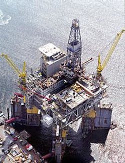
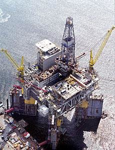
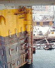
A study of the pile installed on an offshore platform operating in Angola illustrates the dynamic response of these piles to tidal level changes (Figs. 1 and 2).
Offshore water disposal
Even though regulations allow platforms to discharge produced water into offshore waters, regulatory agencies limit the hydrocarbon content in this discharge to prevent pollution.
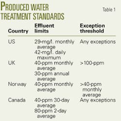
Table 1 compares produced-water treatment standards, as published in an August 2001 Canadian Association of Petroleum Producers technical report.
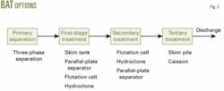
Fig. 3 illustrates the produced-water treatment sequence and the best available technology (BAT) options. Offshore platforms typically use this treatment sequence, which is recommended by the Paris commission (Parcom) and the US Environmental Protection Agency (EPA).
While some operators use piles as a part of the produced-water treatment system, most use piles only to treat deck drainage prior its discharge.
Types of piles
The industry has done significant research on disposal-pile designs and currently the market has several kinds of disposal piles available.
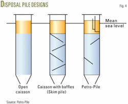
The simplest and earliest version of the disposal pile is an open caisson without any internal baffles. This open caisson is a large-diameter vertical pipe suspended from the platform.
Another version of the disposal pile, generally known as skim pile, is an open caisson with some internal baffles that reduce the length of the settling section. In a skim pile, designers sometimes install risers inside the caisson to collect oil particles.
A third type of disposal pile is the Petro-Pile, a patented design of Petrex Inc., Harvey, La. This pile contains a quiet chamber (oil bucket) for collecting the separated oil. The main advantage of the quiet chamber is that it prevents any possibility for the separated oil to remix with the incoming produced and drain water. Also it has fewer baffles compared to the traditional skim pile and its open flow area is larger.
Fig. 4 shows the general design of the different piles.
Pile sizes
The sizing of the pile involves fixing the pile diameter and length for the given operating conditions. The diameter needs to be large enough to handle the incoming flow from the deck drain and produced water. The deck drain may carry rainwater and also deck wash-down water.
In the pile, oil droplets rise upwards and separate from the continuous water phase. The pile design should be based on a simple vertical gravity separator with the assumption that the upward oil particle velocity will overcome the down flow of the water.
The following equation for the minimum required pile diameter assumes that the terminal oil-particle velocity is at least equal to the down flow water velocity.
di2 = 2,378RwAd/∆SGxDm2
In the equation:
• Rw - Rainwater intensity, in./hr
• Ad - Exposed deck area, sq ft
• ∆SG - Difference in water and oil specific gravity
• Dm - Oil droplet diameter, μm
• di - Pile internal diameter, in.
The pile length should be long enough to hold the drain and produced water for a sufficient time. The length also should have a provision for the tidal level changes and occasional storm surges.
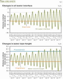
Fig. 5 shows a typical curve for the tidal level changes at Lobito, Angola.
The height of oil and water layer inside the pile depends on fixed values of the normal high tide (HN).
The changes in tidal levels for all locations are difficult to generalize but may be in the range of about ±0.5 m above and below the normal high-tide level.
The piles generally have an inlet of the deck drain and produced water at about 3 ft below the oil-water interface so that the incoming fluid does not disturb the interface.
For the best separation, the design should incorporate the following two points:
1. No water should enter the separated oil phase
2. The drain and produced-water inlet should always be below the oil-water interface.
Angola case
The nature of the dynamic response of all types of piles is the same. A study of a pile on a platform off Angola illustrates the effect of tidal level changes on the oil and water layer’s thickness.
This platform has a 41,341 sq ft exposed deck area and the pile treats the deck drained water but not the produced water. The pile design assumes a continuous rainfall of 2 in./hr and a 1.5-m normal high tide at Luanda, Angola.
In the pile, the separated oil level keeps rising until it reaches the slot level on the quiet chamber. Once reached, the oil drops into the chamber so that clean oil can be collected. This prevents the possibility for the separated oil to mix with the incoming water.
The study looked at the dynamic response of the oil-water interface with changes in tidal level during 10 days in January 2005. Fig. 6a is the dynamic response of oil-water interface and Fig. 6b shows the dynamic response of the water layer (pile full of water).
The figures show that the high and low tides occur twice each day. The horizontal straight line represents the fixed-drain inlet levels and the curve represents changes in the oil-water interface level with changes in tidal level.
During high tide, the oil-water interface always will remain above the drain inlet and during the low tide the oil-water interface will be below the drain inlet. This means that during the low tide there is a possibility that the incoming drain water will disturb the oil-water interface.
In the study the assumption is that the following two events occur simultaneously,
1. The rain continuously falls at 2 in./hr.
2. Oil enters the pile at a continuous rate.
In normal operating conditions, the chances of continuous oil spills on the platform are relatively low, but still whenever high amounts of oil are spilled on the platform during low tide there is a possibility of disturbing the oil-water interface.
This is the limiting condition for designing the oil take-out point in the disposal pile. One can always adjust the slot height in the Petro-Pile and an operator may have to change this height regularly, depending on the conditions.
This is one of the advantages of the Petro-Pile not available in other disposal piles.
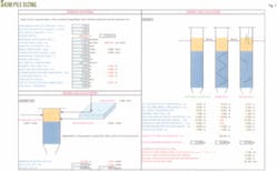
A simple worksheet can be made with MS-Excel for pile sizing and to study the dynamic response of pile against the changes in tidal levels. Fig. 7 shows the computer screen for such a worksheet.
Considerations
This article points out the fact that while designing the disposal pile, one must consider the effect of tidal levels on different parameters.
In the Angola example, a low tide will affect the oil-water interface with respect to fixed drain inlet, while the high tide will affect the slot height. While designing the disposal pile, one must locate the drain inlet height so that the average low tide will not disturb the oil-water interface.
In the Petro-Pile design, one has to design the slot height for the quiet chamber for the high tide level, although one can adjust the slot height based on changing tidal levels. But this pile design does not allow one to adjust the drain inlet height. One can avoid this problem if the proper drain inlet height is selected in the pile design stage.✦
The authors
Kaushal Shah is a design engineer in the offshore division of Daewoo Shipbuilding & Marine Engineering Co. Ltd, Geoje-Si, South Korea. His work involves the procurement, detail design, and construction activities on offshore platform and LPG vessel projects. Shah has a MS in process engineering from IIT-Delhi, India.
Jae-Young Lee is the team leader for ten mechanical engineers in the offshore division of Daewoo Shipbuilding & Marine Engineering Co. Ltd, Geoje-Si, South Korea. He has 15 years of experience in offshore design and specializes in detail design of rotating equipment.
