Long-offset techniques head advances in marine electromagnetic surveying
An electromagnetic (EM) technique for marine hydrocarbon prospecting, first used commercially in November 2002, has gained wide industry acceptance.
The technique identifies resistive reservoirs by measuring the energy received at long source-receiver offset distances (approximately greater than three times the reservoir depth).
Statoil researchers first showed the potential of the approach during the late 1990s. Electromagnetic Geoservices AS (emgs), based in Trondheim, Norway, was formed in 2002 to commercialize the technique.
In the past few years, many improvements have been made to the operating practices, survey equipment, and data-processing techniques. These developments have resulted in the acquisition of a considerable body of high-quality data under a wide range of conditions and the delivery of sophisticated answer products that now include depth-migrated images of resistive subsurface bodies.
Introduction
The feasibility of using controlled-source electromagnetic (CSEM) surveying for hydrocarbon prospecting has been debated for many years.
Academic research into general CSEM techniques began in the 1980s. However, it was believed that energy reflected from the surface of the sea, the “airwave,” would mask energy from the subsurface in anything other than relatively deep water and that the signal could not penetrate very far in highly conductive sediments.1-3
Terje Eidesmo and Svein Ellingsrud took an interest in the technique in 1997 while working at the Statoil research center in Trondheim. Working with others, they modeled the behavior of EM propagation at both long and short offsets, with encouraging results.
They concluded that, under the right conditions, resistive bodies in the subsurface could guide EM energy over long distances with low levels of attenuation. The implication was that CSEM data recorded with long source-receiver offsets could be used to detect resistivity anomalies on the scale of many commercial hydrocarbon reservoirs.
Modeling showed that, in relatively deep water, measurements could be made despite the airwave. The initial hopes were, therefore, for a technique that would complement deepwater seismic data by identifying the location of resistive hydrocarbon-bearing formations within structures. Similarities between long-offset CSEM surveying and wellbore resistivity logging led to the new technique being described as seabed logging.
In November 2000, the first practical demonstration of the technique developed by Statoil was completed off the coast of Angola in about 1,200 m of water above a known shallow hydrocarbon reservoir.3
Seabed receivers were positioned to detect signals, from a towed source, at offsets in excess of approximately three times the burial depth of the target formations. This survey geometry was planned to optimize the response to energy guided through hydrocarbon-bearing formations. Data were recorded with equipment supplied by several research centers in the US and the UK.
This article describes the rapid and dramatic developments in the long-offset CSEM technique that have occurred during the last three years. Sophisticated interpretation products are described with examples of successful applications, and a well-established acquisition, quality control, processing, and interpretation workflow is presented.
In particular, the techniques developed by emgs for rigorously computing depth-migrated images of the subsurface are shown.4
Testing times
A second long offset survey, recorded in the North Sea for Statoil, Shell, and Enterprise Oil in October 2001, was the first test of the Statoil technique as a commercial concept.
Results from these trials were encouraging, and more than 20 companies have used seabed logging data since then.
The Linerle discovery northeast of Norne is one of several prospects on the Norwegian continental shelf surveyed during 2003. The operator, Statoil, had comprehensive 3D and 4-component seismic data for the area that showed a promising structure in 300 m of water. There was evidence of hydrocarbons nearby but no direct evidence of hydrocarbons in the structure.
The long offset EM survey showed regions of high resistivity. A discovery well subsequently proved an oil column 20 m thick, confirming the seabed logging data. Statoil then made public its “plans to make extensive use of this solution.”5
Tage Rosten, Statoil project leader for seabed logging, points out that the technique is now being used on a regular basis to complement seismic data for exploration and early-phase development: “Applications include delineation and ranking of prospects at locations with reasonable structural control from seismic data. We have several examples where predrill predictions have determined the drill or drop decisions for exploration wells.”
Shell is focusing on merging seismic with nonseismic methods, including seabed logging. Mike Naylor, Shell’s exploration technical director, says, “I am confident that nonseismic technologies like seabed logging will provide a much-needed renaissance for exploration.”6
Data from offshore Brazil, Norway, West Africa, Egypt, and the Far East have been evaluated, and Shell is now looking at how best to integrate seabed logging and other technologies into the whole technical workflow. Dirk Smit, Shell’s exploration technology manager, is clear about the value of the technique: “We have tests, data, and evaluations from many regions. We see the technology’s potential very clearly and have incorporated it in our processes when deciding what technologies to apply where.”
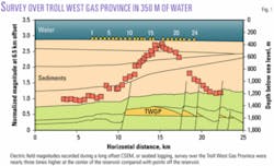
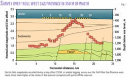
In December 2003, calibration surveys were recorded for Hydro and Statoil over the Norwegian Troll West gas province (TWGP) in 350 m of water (Fig. 1). The objective was to provide unequivocal evidence that the technique worked in less than 500 m of water.
A suspected high-resistivity (up to 250 ohm-m) reservoir buried at relatively shallow depths (about 1,200 m) presented favorable conditions for doing this. Widely publicized results from these surveys offered convincing proof that, even in relatively shallow water, the technique had practical applications in locating hydrocarbons.7-11
Following the TWGP survey, more than 100 commercial long-offset EM surveys have been conducted in 200 to 3,100 m of water and in latitudes ranging from the tropics to the arctic.
In each of the 25 cases where a well has been drilled in the survey area, the information found by drilling has corroborated the seabed-logging predictions. At least one discovery has been made after seabed logging results indicated that the area being explored without success should be enlarged; a discovery well was subsequently drilled.
However, not all stories have such happy endings, and several dry wells have been drilled in areas where resistive anomalies were not observed in emgs’ survey results.
Despite the exploration outcomes, these wells add further evidence that seabed logging is a reliable exploration tool.
Scanning and imaging
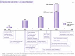
The uptake of long-offset CSEM surveys has accelerated dramatically in the last 2 years as majors, national oil companies, and independents alike have seen the potential of the technique for reducing exploration risks and cutting finding costs (Fig. 2).
As confidence in seabed logging results grows, regulators and operators are moving from evaluating and calibrating the technique in known fields to bringing it into mainstream exploration.
With rig availability currently at low levels and spread rates up to $450,000/day, the value of any additional information about exploration prospects is clear. Indeed, one company ran a survey six weeks before a planned drilling date to confirm its decision to drill.
National and governmental agencies with responsibility for access to offshore acreage have started to accept the long-offset EM technique for evaluating the potential of license blocks.
One national petroleum directorate has recently demonstrated its level of confidence in the technique. The directorate released an operator from its obligation to drill an appraisal well on condition that a seabed logging survey was run to evaluate the potential of the area.
In West Africa and Brazil, substantial surveys have been recorded before license rounds. Customers are using the data to improve the decisions made on whether to bid on a block and how much to bid. Smaller companies, by adding an additional control to limited 2D seismic data, can bid with increasing confidence and without the cost of the 3D surveys that only the large players can afford.
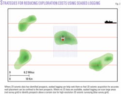
Companies are increasingly planning reconnaissance surveys in areas with poor or no seismic coverage. In such “scanning” applications, receiver lines are widely spaced in open grids but sufficiently close together to ensure that any reservoir exceeding a certain size will be sampled and seen as a resistivity anomaly (Fig. 3). Seismic and further seabed logging can then be used to add detail to likely prospects.
Svein Johnstad, Hydro O&E’s research project manager with responsibility for seabed logging, is clear on the importance of the technique.
“In many basins, it is a valuable method. Particularly when you have simple shale and sand lithology, it is a method that can easily be applied for seeing high-resistivity hydrocarbon layers. It is a pretty safe method in deep water and with hydrocarbon reservoirs of a reasonable size that are not buried too deeply. The method can also be applied, with some precautions, in shallower water depths.”
Johnstad is also realistic about where there are still challenges to be addressed. Specifically, he notes that research is required to separate out the effects of resistive features such as salt and to improve the response in shallow water.
Reflecting these views, the focus at emgs is now on understanding more about the potential and the limitations of the technique and how to deal with more complicated geology and shallower water.
Processing and interpretation developments are aimed at integrating the data with commercial modeling and interpretation packages and presenting the results as images that are familiar to geophysicists. Developments in these areas are best explained in the context of the physics behind EM energy in the subsurface and by comparison with seismic techniques.
Guiding principles
The unique application of the CSEM techniques patented by emgs exploits the tendency for relatively resistive layers in the subsurface to guide low-frequency EM energy sent from a source to a receiver at intermediate to long offsets.
EM energy propagating in conductive beds such as overburden formations is rapidly attenuated. And the velocity of propagation varies greatly between resistive and conductive formations, far more than for an equivalent seismic wave. Even though the energy in the subsurface may be attenuated and weak, it is reflected and refracted strongly at resistivity contrasts.
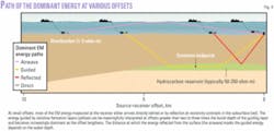
Under the right circumstances, energy reaching a reservoir will be guided along, and travel at a much greater velocity through resistive beds with comparatively low attenuation. This is the dominant path for low-frequency EM energy emitted by a source close to the seabed and reaching a receiver several kilometers distant (Fig. 4).
Just as light entering an optical fiber at a sufficiently shallow angle is guided with little loss to the outside of the fiber, so EM energy arriving at layers of rock from long offsets is guided with low attenuation within relatively resistive layers.
But, unlike in an optical fiber that is optimized to retain light, EM energy leaks from resistive beds. Receivers on the seabed record the energy that is emitted from beds that are guiding the energy. The presence of subsurface resistive bodies such as hydrocarbon reservoirs is revealed by the “glow” of energy that is given off.
The size of the signal at the receiver depends on the volume and resistivity of the body, and it is greater for shallow reservoirs. The response, therefore, has a strong correlation to these important properties, which contribute the commercial viability of a reservoir.
Surveying the options
Planning a seabed logging survey starts with plane-layer (1D) modeling to test the feasibility of recording a successful survey under given conditions.
Water depth, depth to target, reservoir thickness, EM frequencies, and subsurface resistivity changes are taken into consideration. Plane layer modeling gives the best-case response. If it shows that the target could yield a measurable response, 3D modeling is performed to determine the likelihood of the survey objectives being met and, if appropriate, to help plan the survey.
During data acquisition, EM energy is emitted by a horizontal electric dipole (HED) manufactured exclusively for emgs by Siemens in Trondheim. The HED is deployed on a 5,000-m umbilical from a winch that has been developed from proven technology used in remotely operated vehicle deployment.
The risks from manual handling of equipment are minimized by the use of integrated source and towfish handling equipment. The HED is towed 30 m above the seabed and delivers up to 1,250 A at water depths down to 3,500 m. A continuous signal of pulses, with frequency content optimized for the target depth, is used to improve the higher frequency content by stacking data.
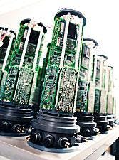
Receivers are normally positioned so that if one fails, data from others is sufficient to compute the result. Current third-generation receivers make two independent measurements of each component of the horizontal electric field that can be stacked to increase survey speeds. However, the redundancy of each electric field measurement also means that survey quality is not compromised if an acquisition channel should fail.
The receivers also measure the horizontal magnetic field strength to enable computation of the up-down separation of the EM energy reflected at the water-air interface, which improves data quality in shallow water (Fig. 5).
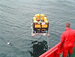
During a survey, the receivers are lifted overboard and dropped on station to sink freely to the seabed under the weight of temporary concrete anchors. When all the receivers are in position, the towfish is pulled along the predefined survey line. Data are recorded in the datalogger section of each receiver as the subsurface is illuminated from continuously varying source offsets (Fig. 6).
The optimum receiver positions are initially determined by 3D forward modeling but may be altered during the survey on the basis of real-time processing and quality control of the data. When the survey has been completed, a hydroacoustic signal instructs the receivers to release their concrete anchors. The receivers then float up and are collected as the boat retraces its path along the survey line.
Considerable effort has been put into reducing the environmental impact of long-offset EM surveys. For example, the HED delivers large currents without injury to marine life; and the third-generation receiver anchors are made from a patented, soluble cement mix that dissolves into environmentally benign products to leave no footprint after the survey. The dissolving anchors also ensure that the receivers eventually float to the surface if the anchor-release mechanism ever fails.
Data are downloaded within 15 min of retrieving each receiver from the sea. Onboard preprocessing and quality control help to ensure that the survey objectives can be met using the data available.
If the objectives are not being met, the survey can be redesigned in real time, for example, by the acquisition of additional lines. Processing turnaround time is improved by reducing the volume of data sent ashore by up to 100 times before it is transmitted by satellite data link to the emgs processing center in Trondheim. Data are available within hours of acquisition.
Developments in acquisition efficiency and quality have been matched by improvements in processed answer products and interpretations. Standard survey results are displayed as EM magnitude versus offset (MVO) and phase versus offset (PVO) plots that indicate the position on the survey line of any underlying resistive anomalies.
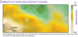
Summary plots on seabed maps show the survey results and the prospect outline (Fig. 7). Customers receive their reports and data in SEG-Y format. Processing and interpretation yield other deliverables such as 3D interpolations from parallel survey lines and plots combined with seismic sections.
Migration in depth
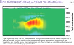
One of the most significant advances in marine EM hydrocarbon prospecting has been the development of methods for depth migrating the data to create images that show the horizontal and vertical positions of resistivity features (Fig. 8).
Superficially, the task of depth migrating EM survey data appears similar to that for wave-equation prestack depth migration of seabed seismic data. Indeed, migration of EM data is possible in a similar fashion if the elastic wave equation is replaced by Maxwell equations. However, in practice, depth migration of EM data is much more challenging because of the fundamental differences in the way that EM energy propagates in the subsurface.
Attenuation of EM energy is a function of frequency and formation conductivity. Frequencies in the range 0.25 to 2 Hz are typically used to penetrate lower-resistivity overburden formations to the depths where hydrocarbon accumulations may be found.
Electromagnetic waves in the subsurface travel much slower than they do in free space, and at these frequencies the typical wavelengths are in the region of several kilometers.
The subsurface is also highly dispersive, with different frequencies having different velocities. The depth resolution of the survey is therefore lower than that of seismic surveys.
Long wavelengths also mean that measurements are made at distances of less than one wavelength, i.e., in the near field of the EM energy. For typical overburden resistivities (1 to 3 ohm-m), the near field may reach several kilometers into the formation. The far-field phase increases linearly with propagation distance (if the local velocity is constant). However, the phase does not necessarily increase linearly with distance in the near-field, which makes depth migration using a velocity model much more complicated than in the seismic case.
A two-step method that uses modified depth-migration techniques to constrain an inversion of the EM data has been developed to create images of resistive bodies from seabed-logging data.
The first of the two steps, depth migration, involves a propagation step to calculate the EM field in the subsurface and a correlation step to perform the imaging.
The field propagated from the EM source is computed using full 3D Maxwell equations. This overcomes any errors in computing phase velocity in the near field that are inherent in lower dimensional methods that are based on 1D or 2D propagation. Even when the field being investigated is limited to a 2D plane containing the survey line, errors of several hundred meters in the migrated depth can be introduced by such approximations.
Imaging techniques used in seismic depth migration that correlate the up- and downgoing energy assume that energy is reflected from impedance contrasts. These correlation techniques are not well suited to imaging reservoirs using EM energy guided by resistive formations. Incorrect use of seismic correlation methods for imaging can introduce additional errors of several hundred meters. Modifying the standard imaging condition by introducing a nonlocal imaging operator improves depth migration of the resistivity image because the physics is more fully respected in this approach.
The second of the two steps is similar to an inversion-systematic forward modeling that seeks a model to explain the survey data. The depth-migrated resistivity from the first step is used to constrain the number of possible models, which reduces the overall computing time.
Proprietary depth-migration and inversion software solves for generally nonhomogeneous media and for horizontal and vertical anisotropy. The technique has been well calibrated using tests on synthetic data and calibration surveys over known reservoirs.
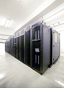
Solving Maxwell equations in 3D is much more processor intensive than computing lower dimensional solutions. Emgs has invested in a high-performance computing cluster to handle current 2D line processing, but it has the capacity to be expanded to migrate and invert 3D acquisition data in the near future (Fig. 9).
This new two-step depth migration increases the confidence in the final interpretation of the depth and extent of any resistive bodies. An example of how this method has been used to depth migrate the Troll field dataset and the corresponding results will be presented at the SEG 75th Annual Exposition and Annual Meeting, Nov. 6-11, 2005, in Houston.
A bright future
Even as seabed logging is becoming a relatively well-understood technique, further developments are being pursued.
It is no surprise, given the history of seismic techniques, that the next advance in acquisition will be true 3D surveys. In these, the source will be towed in any optimum direction over a grid of seabed receivers to create a full, depth-migrated, 3D resistivity volume. Dirk Smit of Shell already has this on his wish list: “The full capability of 3D imaging and inversion of this data over various frequency bandwidths is very important.”
The value of long-offset EM surveys for finding and delineating hydrocarbon reservoirs has been demonstrated, but new applications are also expected. For example, the technique could be used to identify resistive drilling hazards in deep water such as shallow gas or hydrates.
To promote the increased use of 3D surveys, and scanning of larger areas, efforts are being focused on increasing the efficiency of data acquisition to reduce operating times and enable large survey areas to be covered.
With the commissioning of its third survey vessel in the first quarter of 2006, emgs will launch a new integrated acquisition system. This will provide a single interface for all aspects of offshore acquisition, including towfish navigation; setting up the source pulse frequency and shape; modeling; data downloading; and preprocessing. The new acquisition system will help to reduce the number of specialists required on board for conducting a survey and improve acquisition efficiency and quality.
As seabed logging data become increasingly important in all phases of exploration, the technique’s success will depend on the ability to share data with industry-standard applications. Achieving this will ensure that convergence between seabed logging and other exploration techniques occurs to benefit the exploration community everywhere.✦
References
1. Eidesmo, T., Ellingsrud, S., MacGregor, L.M., Constable, S., Sinha, M.C., Johansen, S., and Kong, F.N., “Seabed logging (SBL), a new method for remote and direct identification of hydrocarbon-filled layers in deepwater areas,” First Break, Vol. 20, 2002, pp. 144-152.
2. Anon., “How electromagnetic sounding technique could be coming to hydrocarbon E&P,” First Break, Vol. 20, 2002, pp. 142-143.
3. Eidesmo, T., Ellingsrud, S., MacGregor, L.M., Constable, S., Sinha, M.C., Johansen, S., Westerdahl, H., and Kong, F.N., “Remote detection of hydrocarbon-filled layers using marine controlled-source electromagnetic sounding,” EAGE 64th Conference and Exhibition, Florence, Italy, May 27-30, 2002.
4. Mittet R., Maaø F., Aakervik, O.M., and Ellingsrud, S., “A two-step approach to depth migration of low-frequency electromagnetic data,” SEG/Houston, 2005, Technical Program, Session EM1, CSEM For Exploration 1: Modeling, Inversion, Imaging, Nov. 8, 2005.
5. Statoil, “Annual report and accounts,” 2004, p. 32.
6. Anonymous, “An exploration renaissance,” Changes, Vol. 6, No. 1, 2005, pp. 4-7.
7. Farrelly, B., Ringstad, C., Johanstad, S.E., and Ellingsrud, S., “Remote characterization of hydrocarbon-filled reservoirs at the Troll field by seabed logging,” EAGE Fall Research Workshop, Rhodes, Greece, September 2004.
8. Amundsen, H.E.F., Johansen, S., and Røsten, T., “A seabed-logging (SBL) calibration survey over the Troll gas field,” 66th EAGE Conference and Exhibition, Paris, France, June 2004.
9. Johansen, S., Amundsen, H.E.F., Røsten, T., Ellingsrud, S., Eidesmo, T., and Bhuyian, A.H., “Subsurface hydrocarbons detected by electromagnetic sounding,” First Break, Vol. 23, 2005, pp. 31-36.
10. Johnstad, S.E., Farrelly, B.A., and Ringstad, C., “Seabed logging on the North Sea Troll field,” OTC Paper 17661, Houston, May 2005.
11. Johansen, S.E., and Amundsen, H.E.F., “Reducing exploration risk,” Hart’s E&P, May 2005, pp. 78-79.
The authors
Terje Eidesmo began working for Statoil in 1991 as a petrophysicist with responsibility for research projects. By 1995, he was project manager at Statoil’s research center. His main areas of expertise were nuclear magnetic resonance logging and EM technology. He was a pioneer in Statoil’s work on seabed logging and was a founder of emgs in 2002. He has a PhD in physics from the University of Trondheim and holds a petrophysics professorship there.
Svein Ellingsrud worked as a service engineer for IBM and Norsk Hydro before he started studying physics at the Norwegian University of Science and Technology, Trondheim. After finishing an MSc, he studied for a PhD in physics and in 1992 was employed as a research petrophysicist working on rock physics and electromagnetic methods for downwhole monitoring at the Statoil research and development center in Trondheim. With Terje Eidesmo he was one of the seabed-logging innovators at Statoil in 1997 and was a cofounder of emgs. He is responsible for research and development in the company.
Ståle E. Johansen, a cofounder, is responsible for geology and geophysics in emgs. He previously worked for Esso Norge and Statoil, mainly in exploration, and later moved to Statoil’s research department. He received an MSc in geophysics from the University of Bergen and a PhD in geophysics from the University of Oslo. He holds a part-time professorship in geophysics at the University of Trondheim.
Rune Mittet, emgs research adviser, started working on seismic modeling and seismic prestack migration methods as a research scientist at SINTEF Petroleum Research in 1985. From 1996 to 2000, he was a consultant on seismic modeling problems for Statoil and PGS-Research before joining PGS-Research in 2000. There he worked on the development of a new 3D prestack migration scheme for implementation on large-scale Linux clusters. He has a PhD in physics from the University of Trondheim.
