Carbon steel with inhibition chosen for sour-gas corrosion management
QATAR OFFSHORE-1
Qatar Shell GTL Ltd. decided to use a carbon steel pipeline with inhibition to address corrosion-control problems caused by sour gas produced as part of its Pearl GTL project. Part 1 of this series, details the selection process used in making the decision. Three corrosion-control options were considered: corrosion-resistant alloy (CRA) pipelines; carbon steel pipelines with corrosion control by pH stabilization; and carbon steel pipelines with corrosion control by inhibition.
Part 2 will detail the corrosion modeling used for design of the pipeline.
The project
Pearl GTL is to supply produced fluids from two blocks in the North Field, off Qatar. Current development plans call for identical single offshore wellhead platforms in each block, neither having processing facilities. Two trunklines, one from each platform, will export wet sour gas and condensate.
The process for selecting suitable corrosion control options initially looked at technical feasibility and then considered whether any of the options could be quickly excluded on the basis of scheduling difficulties, environmental issues, local content requirements, or cost before beginning a more detailed assessment. This process led to the choice of carbon steel with inhibition as the corrosion-control option for this pipeline.
The design process for carbon steel with inhibition includes:
• A review the failure modes to determine which must be considered for the specific application.1
• A definition of the base case.
• The selection of a suitable corrosion model.2
• Modeling, including a sensitivity assessment to assess factors that could have a major impact on the assessed corrosion rate.3
• Determination of required inhibitor system availability and corrosion allowance.
• Definition of high-level inhibitor system availability management requirements.4
The corrosion-management system also needed to be transferred to operations, including corrosion monitoring, data management, the corrosion-control manual, and corrosion assessment for integrity purposes.
Certain combinations of flow regime, velocity, and chloride content of the produced water require operational pigging, and batch corrosion inhibition (BI), in addition to continuously injected corrosion inhibition (CI).
CRA pipelines
Design conditions of 1.6 barg partial pressure of H2S, temperature of 86° C., a possible high chloride concentration, and pH down to 3.5 led to the selection of alloy 825 clad carbon steel for the CRA option. Clad CRA pipelines are proven technology and this alloy was considered suitable for these operating conditions. The cost of alloy 825 heavily depends on the market price of nickel. At the time of the assessment, the clad CRA material was 2.8 times the price of carbon steel material.
Capital and operational expenditure considerations dictated the economic choice between carbon steel and CRA. The capital expenditure difference between the CRA option and the carbon steel option had to be offset by the additional life-cycle operating costs of the corrosion control system. The life-cycle operating costs for the two possible carbon steel options were determined to be far less than the life-cycle cost of the CRA option. This was consistent with previous experience on similar projects.
Carbon steel, pH stabilization
Corrosion control by pH stabilization has been studied in joint industry projects over the past 11 years.5- 9 Review of these data, together with operational feedback from companies operating the majority of the pipelines using pH stabilization for corrosion control, led to the following conclusions:
• Corrosion control by pH stabilization is technically proven for sweet wet-gas developments, where no formation water is produced.
• In sweet wet-gas service, pH stabilization can be used as a once-through system (no recycle of the chemicals), but this is commercially unattractive when compared with conventional inhibition.
• Where pH stabilization in a recycle mode is technically viable, it has much lower operating costs than inhibition systems.
• pH stabilization is not effective if formation water is produced.
• Corrosion control by pH stabilization in sour service is not yet technically proven at the levels of H2S and CO2 found in this project.
The type of hydrate control to be used was also reviewed. Kinetic hydrate inhibitor (KHI) was selected, which would only be required for the 6 winter months of the year when sea temperatures are below hydrate-formation temperature.
The KHI is injected as a once-through system, without recycle.
A recycled pH stabilization system is therefore not possible.
KHI offers large capital expenditure and life-cycle cost savings for this development when compared with an MEG-based system (MEG pipeline, conventional MEG regeneration system, and vacuum-regeneration system).
Without a hydrate-control recycle system, considering that pH control is technically unproven for sour service, and given the unknowns about formation water production, pH control was not a viable option for this project.
Control by inhibition
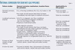
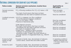
Table 1 shows the potential corrosion mechanisms of carbon steel pipelines.
• Acid returns. Acids can destroy the iron sulfide films, which otherwise protect the steel from further corrosion. The corrosion inhibitor will be tested at the design-level chloride concentration, equivalent to the chloride level in the formation water. Clean-up targets for this project were provisionally set to pH ≥ 4 and chloride less than design level.
Formation water breakthrough will cause high chloride content at the reservoir. This will decrease through the system as more water is condensed (predicted pipeline-entry chloride content in these cases is 123,000 ppm). Field experience shows that more stringent corrosion-control practices (which may include high rates of CI, BI, and operational pigging) are required when the chloride level is greater than 10,000 ppm. The type of water being produced determines acid returns corrosion control requirements.
When only condensation water is produced:
1. The wells are cleaned until the pH ≥ 4 and chloride less than design level is reached. Fluids are not flowed to the pipeline during cleanup.
2. Stringent corrosion control is applied until the chloride level drops below 10,000 ppm on a continuous basis; these are the same as the corrosion controls applicable if formation water is produced.
3. Once below 10,000 ppm, the corrosion control scheme reverts to that applicable for condensation water only (CI injected at optimized rates).
If formation water and condensation water are produced:
1. The wells are cleaned until the pH ≥ 4 and chloride less than design level is reached. Fluids are not flowed to the pipeline during clean up.
2. The corrosion controls applicable when formation water is produced are then applied.
It should also be recognized that even after the fluids have reached the required pH and chlorides levels, intermittent slugs of acid returns will be produced. Over this period continued pH and chloride monitoring are required. Experience with Shell Canada demonstrates that the level of chloride can have a large impact on corrosion rates in the system, as high levels of chloride can destroy the protective iron sulfide films.
• H2S/CO2 corrosion. The sour corrosion regime dictates that an iron sulfide film will be produced. These films are thin and tightly adherent to the steel surface. They also have a very low diffusion of H2S or CO2 through the film. This film provides protection to the carbon steel as long as it’s in place. There is always a risk of damage to the film, however, and the corrosion rates predicted by the model take this risk into account.
In normal flowing conditions, the continuous inhibitor provides protection to any damaged areas of the iron sulfide films. High chlorides (above 10,000 ppm) in a low-flow or stagnant condition are thought to reduce the chemical stability of the iron sulfide films. Back production of completion fluids, acid returns, and formation water can lead to high chloride levels.
If formation water is produced, it will not be possible to keep it out of the lines. The formation water has a high chloride level, above the minimum limit of 10,000 ppm. There are proven operating controls10 for high-chloride sour service conditions; higher levels of CI, operational pigging, and BI. These practices can control corrosion in the lines.
• Under deposit corrosion. Iron sulfide films can break down under deposits. Solids in the fluids entering the line or produced in the line (e.g., reservoir solids, scale particles or corrosion products) must be assessed to determine whether they will be transported through the system. If the solids drop out, they must be removed from the line by operational pigging.
Sour corrosion will show a mixture of corrosion products. Some will tightly adhere to the pipe surfaces, some may be loosely adhered and become detached, and others will be very small particles (up to 5 μm) which will be suspended in the water phase or suspended at the water phase-condensate interface. Active corrosion will produce solids, but CI should eliminate any significant buildup.
The reservoirs in this project are not expected to produce solids (being carbonate reservoirs without sand), and effective CI will minimize the level of iron sulfide corrosion products.
• Completion fluids returns. Completion fluids are often high in chlorides or high in other halides, which can damage the protective iron sulfide scales. These should be dealt with in a similar manner as acid returns. Intermittent slugs of completion fluids are also possible.
The strictest control is to prevent these fluids from entering the pipeline until chloride levels are less than 10,000 ppm. This may, however, be economically unattractive. Proven corrosion-control methods in a flowing, higher-level chloride system, such as operational pigging and batch inhibition will allow operation up to the design chloride level with the planned inhibitors.
• Oxygen entry. Oxygen in a sour-gas system could react with the protective iron sulfide scale to form less protective oxide scales, and it could react with H2S to form elemental sulfur. The latter reaction is potentially the more serious, as only small amounts of sulfur are required to produce very high corrosion rates and the sulfur is not consumed in the corrosion process (unlike oxygen in oxidation corrosion). Oxygen is most often introduced with injected chemicals or during pigging operations.
A survey showed that, although the potential for oxygen-related corrosion is recognized in sour-gas pipelines, in practice no operator takes specific measures to limit the amount of oxygen introduced with injected chemicals (corrosion inhibitors, kinetic hydrate inhibitors, scale inhibitors).
The relatively small amounts of oxygen introduced (chemicals being typically introduced in ppm levels) and the fact that it will partition between the phases present (gas, oil, condensate, and water) is thought to limit its corrosive effect. Similarly, normal operational practices for pigging operations (purging prior to a pig run, etc.) are thought to be sufficiently robust to keep oxygen entry below damaging levels.
• Bacteria. Poorly treated hydrotest water, poorly treated completion fluids and acidizing fluids, and injection of sump piles or sump tanks back into the process system are the potential sources of bacteria in a gas system.
All fluids entering the system in this project should be adequately treated for bacteria. Fluids from sump piles and tanks will not be reinjected into the process stream; fluids from the sumps will be pumped into transportable tanks and shipped onshore for disposal.
Additionally, because water produced in gas-condensate systems rarely contains the nutrients required to sustain bacterial activity, it may be possible to reduce some bacteria-control requirements. Finally, normal flow velocities in this system will be high enough to avoid stagnant water pools at low points.
Risk summary
Operating practice can control a number of risks. CI can control some risks. Some risks will require operational pigging or BI.
Given these controls, inhibited carbon steel pipelines were considered technically feasible. The conditions are within the existing operating envelope for sour inhibited systems, in terms of temperature, velocities, pH2S, and pCO2. Areas in which this project moves beyond current experience include:
• The diameter and length of the lines.
• The offshore location (most experience being onshore).
• The lack of many known examples of similar lines (inhibited wet gas, sour service, similar diameter). Those that do exist have not been operating very long (oldest 15 years).
• The high chloride content of the produced water.
• The volumes of produced water that could eventually be experienced.
The larger diameter and length mean that the economic consequence of poor inhibition control is much higher (a higher potential deferred production). Risk of poor inhibitor control must therefore be reduced below that currently achieved in onshore systems, requiring a detailed study of inhibitor system availability.
The inspection and corrosion monitoring requirements for offshore sour wet-gas systems will be higher than comparable onshore sour wet-gas systems and higher than comparable offshore sweet wet-gas systems. Corrosion monitoring is also more difficult because techniques that work well in sweet systems do not work in sour systems. Being offshore makes inspection more expensive and difficult and the economic consequence of poor inhibition control much higher (repair being extremely expensive).
The inspection and monitoring requirements will be looked at in more detail during project detail design. Experience with sweet offshore wet-gas pipelines which will be useful in the design process.
The chloride content of the produced water is much higher in this project than the experience base. It is important that all chemicals be selected for this level of chlorides and that the inhibitor qualification tests be carried out in representative fluids. The potential volume is also higher than the experience base of produced water.
Flow modeling in the lines took produced-water volumes into account. Assessment of the flow conditions for transport of water (and solids) in these lines will use industry-accepted criteria and flow modeling. This will lead to more accurate predictions of the transport of liquids (and solids) in the system and update the current criteria for operational pigging and BI.
Because of the uncertainty regarding pH control in sour service and the high capital expenditure cost of clad CRA pipelines, the selected corrosion-control option was carbon steel plus inhibition. Conventional inhibition will be injected offshore directly into the process stream.✦
References
1. Rippon, I.J., “Carbon steel pipeline corrosion engineering: life cycle approach,” NACE Corrosion 2001, Paper No. 01005, Houston.
2. Pots, B.F.M., John, R.C., Rippon, I.J., Simon Thomas, M.J.J., Kapusta, S.D., Girgis, M., and Whitman, T., “Improvements on the De Waard - Milliams corrosion prediction and applications to corrosion management,” NACE Corrosion 2002, Paper No. 02235, Houston.
3. Kapusta, S.D., Pots, B.F.M., and Rippon, I.J., “The application of corrosion prediction models to the design and operation of pipelines,” NACE Corrosion 2004, Paper No. 04633, New Orleans, Mar. 28-Apr. 1, 2004.
4. Rippon, I.J., “Corrosion control system availability management for reduced cost and extended life,” NACE Corrosion 2003, Paper No. 03313, San Diego, Mar. 16-21, 2003.
5. “Kjeller pH-Stabilization Project II - Improved Corrosion Control in Wet Gas Pipelines,” IFE, Final Report, Oct. 2, 2002.
6. Dugstad, A. and Drønen, P., “Efficient Corrosion Control of Gas Condensate Pipelines by pH-Stabilization,” NACE Corrosion 1999, Paper No. 20, Houston.
7. Dugstad, A. and Lunde, L., “Corrosion Mitigation by pH-stabilisation - Applications and Limitations,” 9th Middle East Corrosion Conference, Feb. 12-14, 2001, Bahrain.
8. “Kjeller Sour Gas Project - Corrosion Control Techniques I, Wet Gas Pipelines with High H2S and CO2 Levels,” IFE, Project Proposal, Rev. June 19, 2002.
9. Kvarekvål, J. and Dugstad, A., “Pitting Corrosion Mechanisms on Carbon Steel in Sour Glycol/Water Mixtures,” NACE Corrosion 2004, Paper No. 04737, New Orleans, Mar. 28-Apr. 1, 2004.
10. “Corrosion Mitigation Strategy for Wet Sour Gas Carbon Steel Pipelines,” DEP 31.40.00.19-Gen.
The author
Ian Rippon (ian.rippon@shell.com) is a Principal Corrosion Engineer with Shell Global Solutions International and is based in the Netherlands. He has 25 years experience as a corrosion engineer in the upstream oil and gas business and has worked in a number of different locations around the world. He holds an MSc (1980) from Cambridge University. He is a Fellow of the Institute of Corrosion, NACE International Corrosion Specialist and a Chartered Engineer in the UK. He has worked on a variety of NACE technical committees, principally in the areas of offshore cathodic protection and corrosion management.
LNG Observer circulation to change
With this issue of Oil & Gas Journal, many OGJ subscribers will also receive the final 2005 installment of OGJ’s LNG Observer, a quarterly supplement produced with the widely respected GTI, Des Plaines, Ill.
If you don’t receive a copy of LNG Observer with your subscription:
• Access http://ogj.pennnet.com/articles/print_toc.cfm?p=94 after Oct. 10, 2005, to read it online;
• Write [email protected] to submit your e-mail address so that your name can be added to the circulation list.
NOTE: With publication of the January-March 2006 LNG Observer, circulation will become totally electronic. To continue receiving LNG Observer, an OGJ subscriber currently receiving the paper issue should make sure OGJ Subscriptions has an active e-mail address on file.


