Critical Mud Weight—1: Analytical method predicts critical mud weight in horizontal wells
Determining the critical or optimum mud weight is not an easy task, especially when drilling horizontal wells.
Drilling mud weight is an important factor in drilling, demanding significant attention because most of the problems encountered during rotary drilling are either directly or indirectly related to drilling mud.
For horizontal wells, the situation becomes more complex and requires a detailed analysis of the conditions under which different forms of failure will occur due to lack of adequate drilling mud weight.
This first article reviews the fundamentals of the function of drilling mud in drilling horizontal wells. It proposes simplified analytical methods for predicting the critical mud weight in drilling horizontal wells in anisotropic stress regimes, considering different failure modes. The proposed method predicts the factors influencing the critical mud weight for given rock mechanical and in situ properties.
In the second and concluding article, the effects are predicted based on stress regimes, wellbore orientation with respect to the direction of maximum horizontal stress direction and depth of the well. It will be shown that both the well orientation and the prevailing stress regime significantly influence the mud weight.
Role of mud
Drilling mud plays vital role in the successful completion of the drilling process. Mud serves various functions including exerting sufficient hydrostatic pressure against subsurface formations and preventing wellbore instability.
A drilling engineer must select and maintain the most appropriate drilling mud to complete the drilling successfully. Most problems that occur during drilling are related to the drilling mud, either directly or indirectly. If the drilling mud does not perform adequately, it could be necessary to abandon the well, which costs significant time and money. Moreover, without adequate control of the mud weight, it is not possible to create a satisfactorily stable borehole.
Therefore, mud weight is an important factor to control. Determining the optimum mud weight is not easy, however, especially for horizontal wells. In horizontal wells, the situation becomes more complex and requires a detailed analysis of the conditions under which different failures may occur.
The main objective of this study is to present a systematic approach to determining the critical mud weight in drilling of horizontal wells using principles of rock mechanics with the appropriate poroelasticity model.
Underground failure mechanisms
When a wellbore is drilled, the removal of the subsurface rock mass disturbs the original equilibrium of the in situ stresses. The rock surrounding the drilled hole has to carry part of the load that was supported previously by the material removed from the wellbore.
The pressure exerted by the drilling mud, the wellbore inclination and orientation, borehole exposure time, surge and-or swab pressure, and other factors can significantly change the distribution of stresses around the wellbore. When this redistribution of stresses around the wellbore exceeds the strength of the underground formations, it may cause an unstable hole condition, which can present different modes of failures.
Developing a simplified model for determining critical mud weight essentially requires knowledge of the mode of underground rock failures. The conditions and class of failures may be determined from the wellbore stress distribution and the mechanical properties of rock. Various types of failures are identified and discussed in this article.
Shear failure
Shear failure can occur in an active (inward movement during production) or a passive mode (outward movement during pressurization). Shear failure is associated with shearing movement along one or more planes of failure. Borehole collapse is mainly the manifestation of shear failure. Four possible types of compressive shear failure are: breakout shear, toric shear, helical shear failure, and elongated shear failure.
Breakout failure, well known to drilling engineers, occurs due to lack of support from the mud column; the horizontal stresses around the wellbore cause the rock to collapse into the wellbore.
Once a breakout failure has been initiated, it can continue to grow, causing deep and irregular variations in the wellbore diameter. In breakout failure, the tangential stress (circumferential stress, σθ) is the maximum principal stress and radial stress (σr) is the minimum principal stress, i.e., σθ≥σz≥σr.1
Toric shear failure occurs in similar situations to breakout failure, due to lack of support from the mud column. In toric failure, however, the stress from the overburden tends to cause the rock failure, rather than the horizontal stresses. Toric failure occurs when axial stress becomes the maximum principal stress and radial stress is the minimum, i.e., σz≥σθ≥σr.1
Helical shear occurs when the vertical stress is balanced by the radial stress exerted from the mud column, but the tangential stresses from the horizontal stresses are insufficient to keep the formation coherent and the formation shears downwards. Helical shear failure occurs when axial stress becomes the maximum principal stress and tangential stress is the minimum stress, i.e., σz≥σ1≥σθ.1
Elongated shear is not as well known as the other forms of failure. It was termed elongated shear due to the shape of the failure region. Elongated shear failure occurs due to excessive mud pressures, with insufficient horizontal stresses to hold the wellbore together, causing the rock to collapse in the region. Elongated shear failure is similar in shape to breakout failure but rotated 90º around the wellbore longitudinal axis so that it is oriented towards the maximum horizontal stress direction and is exaggerated in length (elongated).
Tensile failure
Tensile failure occurs during drilling when mud pressure exceeds the formation pressure, such that it breaks down the formation through tension and initiates fracture. As the mud pressure is increased, the plane along which a fracture will initiate will be that across which the compressive stress is first reduced to zero. In the case of a smooth cylindrical wellbore, this plane must be vertical and perpendicular to the least principal regional stress.2
In regions characterized by active normal faulting, vertical fractures would be formed when mud pressures are less than the overburden pressure; whereas, in regions characterized by active thrust faulting, horizontal fractures will be formed when mud pressures are equal to or greater than the overburden pressure.3
Critical mud weight
During drilling, mud exerts pressure upon the wellbore wall and has a strong effect on the principal stresses acting upon the rock. If the mud pressure falls below a certain level, the wellbore will collapse due to lack of support from the mud column or formation fluid will enter the wellbore. In this situation, the wellbore may collapse in breakout or toric shear failure mode.
If the mud pressure exceeds a certain level, however, the wellbore will fail due to excessive mud pressures. Helical shear, elongated shear, or tensile failure may occur in this situation. It can be inferred that there will be two specific mud weights, one that describes a limiting value below which the wellbore will undergo failure, termed “lower bound” mud weight, and the other that describes the limiting value above which the wellbore will undergo failure, termed “upper bound” mud weight.
If the mud weight is kept between the lower and upper bound, then the wellbore will be in a safe condition. If the mud weight strays outside these limits, then a variety of undesirable effects may occur. These limiting values are known as the critical mud weight, which is determined by the individual conditions for each type of failures.
Lower bound mud weight
The values for breakout and toric shear failure and the formation’s fluid pressure gradient are all lower bounds for the mud weight. Below the formation’s fluid pressure gradient, the wellbore takes a kick; above the formation’s fluid pressure gradient, this could be avoided.
Breakout and toric failure modes are calculated as a single value at which they will occur. The prevailing stress conditions determine which of the two will predominate. Below the lower bound mud weight, all that can be said is that one of them will occur. Above this value, neither will occur.
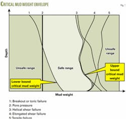
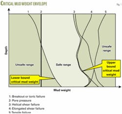
The situation can be explained with the help of Fig. 1. It is undesirable to go below any of these lower bounds, and so the lower bound critical mud weight is the greatest of these at any point. Thus the lower bound mud weight is the mud weight that causes the maximum wellbore pressure below which the wellbore will collapse. The condition of lower bound critical mud weight can be obtained using Mohr-Coulomb failure criteria by considering the appropriate combination of σθ, σz, and σr.
Upper bound mud weight
The upper bound critical mud weight is the mud weight above which some form of failure will occur and below which the wellbore is safe from these failure modes. Failure from helical shear, elongated shear, and tensile failure occurs when the upper bound critical mud weight is exceeded. An individual value of mud pressure is obtained for each type of failure, above which failure will occur, and below which it will not. Thus, the upper bound mud weight is the mud weight that causes the minimum wellbore pressure above which the wellbore will initiate fracture or break down of the formation.
The condition of upper bound critical mud weight can be obtained with Mohr-Coulomb failure criteria by considering the appropriate combination of σθ, σz, and σr and the tensile strength of the formation.
By determining the upper bound and lower bound critical mud weights, one can predict a safe range of mud weights that should be maintained in order to avoid failures during drilling operations. Fig. 1 illustrates the process.
Mathematical modeling
Modeling can be used to quantify the stresses around wellbores and to predict various critical mud weights.
Stresses around deviated wellbores
When a well is drilled into the formation, a rock mass under stress is removed and replaced by a fluid under pressure. Since the fluid pressure in the well does not exactly match the stresses exerted by the removed solid, there will be an alteration in the stress state in the rock surrounding the wellbore. As a result, stress will be concentrated around the wellbore.
Hubert and Willis introduced a technique to analyze the effect of these stresses on hydraulic fracturing.2 For analysis of wellbore breakouts, the formation material is widely assumed to be homogeneous and linearly elastic, with isotropic strength properties.4-6
Attempts have also been made to model the anisotropic strength of rocks with advanced finite-element analysis.7 The assumption of isotropic rock properties is suitable, however, for simplified calculations to study characteristic effects of wellbore trajectory, perforation, and stress regimes on the fracture-initiation pressure.3
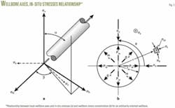
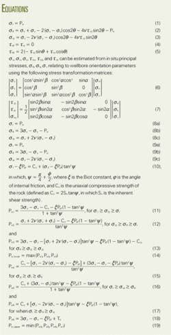
Therefore, assuming homogeneous, linearly elastic, isotropic rocks in which compressive stress and fluid pressure are positive, stresses at the wall of an oriented wellbore (Fig. 2) are derived from solutions presented by several researchers8-10 as shown in the equation box.
Where the wellbore inclination refers to α, wellbore azimuth refers to β, and wellbore orientation refers to any combination of α and β. For horizontal wells, α = 90° from which τxy, τyz, and τzx become zero (Eq. 7).
Equations 1-6 now yield the simplified relations for determining the critical mud weight for a horizontal well, as described below.
Predicting critical mud weight
As discussed above, the critical mud weight is the limiting value of either the lower bound or upper bound mud weight.
The lower bound limits can be obtained by consideration of wellbore stresses to be maximum values, which happens when cos2θ = -1; i.e., for θ = ±90°. Equations 1 to 3 can be expressed for lower bound cases as Equations 8a, b, and c.
Similarly, for the upper bound limits, the wellbore stresses are the minimum values. This happens when cos2θ = 1; i.e., for θ = 0º and 180º. Equations 1 to 3 can be expressed for upper bound cases as Equations 9a, b, and c.
For a poroelastic formation, the Mohr-Coulomb failure criterion11 can be written as Equation 10.
Since the borehole is horizontal; σr, σθ, and σz becomes analogous to the principal stresses σ1, σ2, and σ3, where σ1≥σ2≥σ3. These three stresses can form six different combinations that may cause six possible modes of shear failure. By applying these combinations to the failure criteria, one can derive the required expression of lower bound and upper bound critical mud weight, as presented below.
Determining critical mud weights
Using Equations 8 and 10, the wellbore pressure caused by mud weight is derived as Equations 11-13.
Since this is the lower limit for stability, the well pressure, Pw. should be below the maximum of Pw1, Pw2, and Pw3. Equation 14 shows the lower bound critical mud weight.
In same manner, the equation for determining the upper bound critical mud weight can be derived from Equations 9 and 10, as shown by Equations 15-17.
In addition to shear failure, there can also be tensile failure if the well pressure is large enough to make σθ negative or zero. This is also an upper bound case. For a poroelastic material, the criteria for tensile failure is σ3-ξPpf = To where To is the tensile strength of formation and σ3 is the minimum principal stress, which equals the minimum of σθ.
Substituting σ3 = σθ,min in Equation 9b yields Equation 18.
Since this is the upper limit for stability, the well pressure, Pw can never be above minimum value of Pw4, Pw5, Pw6, and Pw7. Therefore upper bound critical mud weight is shown by Equation 19.
With derived Equation 14 and Equation 19, one can easily calculate the upper bound and lower bound critical mud weights for any stress systems in drilling a horizontal well with the help of wellbore stress concentration equations (Eq. 6 with α = 90º), which are individual equations for Pw for given set of in situ stresses.
It can be inferred, however, that the critical mud weight (either upper bound or lower bound mud weight) is not a single value that could be considered as constant during the whole drilling operation. This parameter varies with the formation mechanical properties, the magnitude of in situ stresses, and above all, the wellbore orientation, specifically the horizontal well orientation with respect to the maximum horizontal stress direction. ✦
References
1. Tan, C.P., and Willoughby, D.R., “Critical mud weight and risk contour plots for designing inclined wells,” SPE Paper 26325, 68th Annual Technology Conference, Houston, Oct. 3-6, 1993, pp. 101-115.
2. Hubbert, M.K., and Willis, D.G., “Mechanics of hydraulic fracturing,” Petroleum Trans., AIME, Vol. 210 (1957), pp. 153-166.
3. Hossain, M.M., Rahman, M.K., and Rahman, S.S., ‘’Hydraulic Fracture Initiation and Propagation: Roles of Wellbore Trajectory, Perforation and Stress Regimes,’’ Journal of Petroleum Science and Engineering, Vol. 27 (2000), pp. 129-149.
4. Aadnoy, B.S., Rogaland, U., and Chenevert, M.E., “Stability of highly inclined boreholes,” SPE/IADC Paper 16052, SPE/IADC Drilling Conference, New Orleans, Mar. 15-18, 1987, pp. 25-41.
5. Hsiao, C., “A study of horizontal wellbore failure,” SPE Paper 16927, 62nd Annual Technical Conference, Dallas, Sept. 27-30, 1987, pp. 481-491.
6. Valko, P., and Economides, M.J., Hydraulic fracture mechanics, Chichester, England: John Wiley and Sons, 1995.
7. Aoki, T., Tan, C.P., and Bamford, W.E., “Effects of deformation and strength anisotropy on borehole failures in saturated shales,” Int. J. of Rock Mech. Min. Sci. & Geomech. Abstr., Vol. 30, No. 7 (1993), pp. 1031-1034.
8. Hossain, M.M., Reservoir Stimulation by Hydraulic Fracturing: Complexities and Remedies with Reference to Initiation and Propagation of Induced and Natural Fracture, PhD thesis, The University of New South Wales, Sydney, Australia, January 2001.
9. Bradley, W.B., “Failure of inclined borehole,” J. of Energy Res. Tech., Trans. ASME, Vol. 101 (1979), pp. 233-239.
10. Richardson, R.M., “Hydraulic fracture in arbitrarily oriented boreholes: An analytical solution,” Proc. Workshop on Hydraulic Fracturing Stress Measurements, Monterey, Calif., December 1981.
11. Earling F., et al., Petroleum Related Rock Mechanics, Elsevier, Amsterdam, 1992.
The author
Md Mofazzal Hossain ([email protected]) is an assistant professor in the petroleum engineering department of King Saud University. He joined the faculty in September 2002. Previously, he worked at the University of New South Wales, Australia, and Reservoir Engineering Research Institute, US. Hossain holds BSc and MSc degrees in naval architecture and marine engineering from Bangladesh University of Engineering and Technology and a PhD in petroleum engineering from the University of New South Wales, Australia. He is a member of SPE.


