Neutron examination techniques applied to pipelines
Information obtained through neutron examination techniques complements that obtained by other techniques (x-rays, TEM, SEM, and magnetic flux leakage) and can reveal significant properties of investigated materials for pipelines, optimizing performance and reliability of components during fabrication, installation, and maintenance.
Adopting neutron techniques is becoming more useful as a method of nanostructural and atomic-scale characterization of materials and components of industrial interest. Especially with reference to such permanent structures as offshore pipelines, it is important that the reliability of welded joints be confirmed. Even the presence of a microcrack following welding can undermine the entire pipeline, with enormous potential economic and ecological consequences.
This article looks at the basic theoretical aspects of neutron diffraction for residual stresses (RS) measurements and small-angle neutron scattering (SANS) for microstructural characterization. Particular attention is paid to precipitates and inhomogeneities in the distribution of elements, which are among the major factors defining a joint’s behavior.
Pipeline applications of both techniques are presented: an RS assessment of pipe weldings and SANS investigations of pipe materials.
Information obtained by such applications can improve design, production, and maintenance and contribute to the development of a nanoscopic safety criterion to forecast possible fractures.
Available tools
A variety of tools is currently available for assessment of defects introduced into the line pipe during fabrication, installation, or operation.
Defects in the weld or the pipe itself, residual stresses (RS), and tensile corrosion are sought, with an eye toward assessing the pipeline’s overall safety.
Cracks are among the most dangerous kinds of defects in pipelines, and the mechanisms of their initiation and growth are still incompletely understood. Stress corrosion cracking (SCC) can arise in different forms-from small, isolated cracks to large crack areas-and increases the risk of pipeline failure. Defects also occur while the pipe wall is under stress due to live pressure.
During the past 2 decades, use of neutrons to probe materials across a wide range of disciplines has become increasingly significant. Such growth is primarily due to the nature of neutrons, which allows the bulk of a sample to be probed in contrast to x-ray techniques that are usually surface-sensitive.
Industrial applications of neutron techniques in engineering and materials science include:
• RS determination and crystallographic texture measurements by neutron diffraction.
• Microstructural characterization by small-angle neutron scattering (SANS).
• Characterization by neutron activation analysis.
• Analysis of fluid flow, evaporation, and condensation in closed metal objects, by dynamic and static neutron radiography.
• Investigation of hydraulic systems by quantitative neutron photogrammetry and dynamic neutron fluoroscopy.
• Study and quality control of thin-layered structures of solid and liquid surfaces by neutron reflectometry.
Neutron diffraction and SANS can also be applied to offshore equipment and materials, giving nondestructive, fundamental information for design, manufacture, and maintenance. In particular, while neutron diffraction is the only tool that allows determining RS in the mass of the sample including welded joints, a SANS-monitoring of the same joints may detect cohesion breaking that leads to internal surface growth and material fracture.
RS by neutron diffraction
Knowing spatial and directional RS distribution in many applications is necessary for determining their influence on a material.1
Stress concentration, in particular tensile stresses, decrease material life and promote SCC and creep. Neutron diffraction represents the most complete method for nondestructive stress measurement of components and helps reduce overly conservative estimates of same, which increase material and replacement costs.
In the strain measurement, a collimated neutron beam (having a wavelength λ) is diffracted by a polycrystalline sample, and then passes through a second collimator and reaches the detector
Both collimators’ slits define the investigated volume, whose normal cross section can be as small as 1 x 1 sq mm or, in certain cases, smaller.
The Bragg law (Equation 1) allows determining the interplanar distance, dhkl. The relations in Equation 2 give the corresponding lattice strain.2
Knowing the elastic constants of the considered material and using the relations of Equation 3 can yield the stress values.
RS induced by welding can compromise the structural integrity of piping that is, consequently, thermally processed. RS have been determined for a 2.25Cr1Mo ferritic arc-welded pipe after relaxation heat treatment.3 The dimensions of the welded pipe are 218 mm OD; 178 mm ID; 355 mm length. Temperature and pressure ranges are, respectively, 350-540° C. and 100-200 barg. This material has fewer weldability problems than austenitic steels.
Creep represents a significant problem in such a component, where manufacture, drawing, and welding processes can induce an RS status.
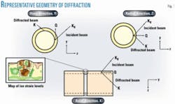
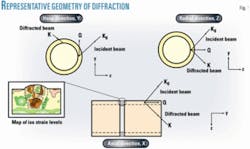
RS measurements by neutron diffraction were performed, before and after the heat treatment, and the pipe was investigated at 2.5, 5, 7.5, and 10 mm depths. Fig. 1 illustrates the representative geometry of the diffraction along the main directions, for neutron diffraction measurement in pipes. The same figure shows how it is possible, by such a technique, to map the iso-strain levels in a welding area and its surroundings.
A clearly asymmetric progression of RS appeared across the welding: Values shifted from one end to the other of the weld zone, following the direction of the passes. Such a trend can be attributed to the asymmetry of the welding process, the fiber that cools last having a higher tensional level as compared to the contiguous regions.
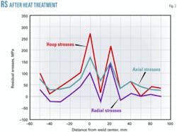
RS after the heat treatment (Fig. 2, with reference to a 5-mm depth) appear to be nothing along the radial direction, while along the axial one they are reduced in comparison to the same depth before the heat treatment, showing a mono-dimensional status. A higher tension level appeared in the hoop direction, due to the cylindrical geometry.
In welding, values up to 250 MPa (instead of the 400 MPa tangential tension seen before the heat treatment) resulted, showing a partial permanence of the initial manufacturing memory.
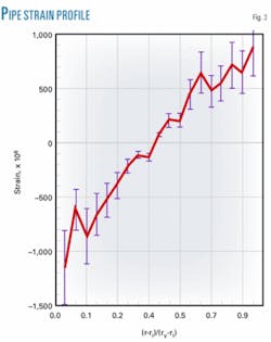
RS measurements by neutron diffraction have been performed in CrMo steel pipe, exposed to an internal pressure of 2,500 barg, with the aim of inducing a strain field in the material. The hoop direction determined the strain profile through the pipe (Fig. 3).
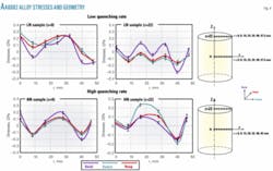
An example showing the correlation between extrusion and quenching effects on the RS field is given by the measurements of two AA6082 extruded samples of cylindrical shape (height, 50 mm; diameter, 100 mm).4
This alloy is widely used in Europe for extruded components of structural applications and is quench sensitive: Too slow a cooling rate reduces quality, while an overly rapid cooling rate can induce heavy distortion of the extruded system.
The specimens were subjected, before the measurements, to an annealing process at high temperature; one sample was then exposed to a low quenching rate, and the other to a high quenching rate. RS measurements were performed corresponding to gauge points aligned along radial straight lines, perpendicular to the axis.
The neutron beam section was 4 x 4 sq mm. Three orthogonal directions of strain were considered: axial, radial, and hoop. The same directions were assumed as the principal ones.
Fig. 4 shows the obtained stresses values (GPa) and the geometry of the experiment.
Neutron diffraction has also been adopted to map the strain surrounding two defects introduced into plates of pipeline grade steel; one into a plate before the uniaxial loading, the second into a plate held at a constant background load, ensuring a stress at the edge of the defect exceeding the elastic limit of the material.5
A section of commercial Grade X-70 pipeline underwent neutron diffraction for RS measurement, x-ray diffraction to study crystallographic texture, and microstructural analysis. The results showed good correlation with the manufacturing steps applied for this type of pipe.6
Intercrystalline and intergranular cracks can be created in pipes and vessels as a consequence either of the construction technique or of the presence of aggressive elements such as H2S. Cracks of remarkable importance can start in narrow welded zones having particular hardness and grow from initially small dimensions to cross the entire pipe thickness.
Neutron diffraction can be successfully used in such cases to determine the spatial and directional distribution of internal RS before and after eventual heat treatments of the material.
SANS
SANS technique allows characterizing materials in the nanoscale range (10-1,000Å) and presents the advantages of being nondestructive and providing information that has a high statistical exactness, due to the averaging that occurs over a macroscopic sample volume. The specimen can be investigated a number of times after exercise or heat-treatments, and the small absorption of neutrons often allows the measurement of materials 1 cm thick.
Fig. 5 shows the scheme of a SANS instrument. The neutron beam is monochromatized by a multidisk velocity selector. The wavelength distribution can be varied by changing the angle between the selector axis and the direction of the same beam. The beam intensity is monitored by a fission chamber and formed by a collimator tube or a variable collimation path system, allowing the optimization of flux and resolution for different sample-to-detector distances. Scattered neutrons are detected by a 64 x 64 pixel two-dimensional, position-sensitive detector (pixel size = 1 sq cm).
The primary data treatment includes the regrouping of the two-dimensional scattering patterns depending on the type of scattering (isotropic or anisotropic), background subtraction, correction for transmission, and normalization to standard samples.
In SANS experiments, the scattered intensity I(q) is measured as a function of the scattering direction, if the elastic scattering dominates the interaction of the neutron and nuclei. The vector, q, corresponds to the momentum transfer. The low limit (qRg<1) behavior of scattering intensity can be expressed with the Guinier relation (Equation 4). Rg can be determined even if I(q) is known only in arbitrary units. In the large q region of scattering, the signal due to the interface between each scatterer and the embedding medium dominates the intensity.
The Porod law (Equation 5) can represent this behavior. The limit of the Porod law is qR>4.
The most important problems related to material strength deal with welded metals, in which fracture risk seems to be much higher than that of the base metal.7-10 The higher risk of joint fracture is due to mechanical stresses (nonuniform) and other factors that prompt aging (thermal treatment, fatigue, corrosion).8 9
The precursory control of material nanostructure seeks degradation trends in order to avoid fracture and predict material lifetime. The information gained by diffraction studies (e. g., RS and microstrains) should be completed by SANS, providing data on the character, number, and size of defects by microbeam scan detection of the nanopores (nanocracks).11-13
The physical basis of fracture process is closely related to nanodefects. The investigation of porosity kinetics-dependent on factors such as stress, temperature, and radiation-is therefore very important.
The nanostructures (precipitates, pores, and dislocation groups) of metal determine the mechanical properties (e.g., creep resistance, joint aging, etc). A nonuniform degradation of material leads to the rapid development of cracks, reducing the lifetime of the joint.
A SANS investigation of very thick components, concerning a NiCrMoV steel (ASTM A 471, Type 2) wheel for traditional energy applications, has been undertaken to study microphase inclusions (precipitates).14 Researchers performed measurements at specific positions where RS in the lattice had also been evaluated.
The investigation showed that the material’s isotropic nanostructure consisted of tiny domains (precipitates, diameter ≈200-300 angstrom; concentration N≈(1-3)1014 cm-3; volume fraction φ≈0.1-0.2%; and total interface area St≈0.2-0.4 sq m). The SANS data also demonstrated that the material had a low concentration of nanodefects, as compared to thermally treated steels, which had an intense formation of precipitates (volume fraction exceeding ~1%).
SANS investigation has also been conducted on P91martensitic steel (9Cr1MoVNb) samples obtained by cutting 24-in. pipes (WT = 14 mm). The samples belong to a test system containing longitudinal weldings in the straight parts, and double axial weldings in the connections.
The system was given 3,000-8,000 hr accelerated creep tests; i.e. to 7,000 start cycles after 100,000 hr (maximum gradient <10° C./min.). The test temperature was ~545-625° C. The test pressure was ~50 barg.
SANS analysis with varied mechanical loading can provide information on the development of nanoscopic and microscopic defects, ranging from dislocations to their groups to voids and cracks.
Thermal treatment will produce the growth of some inclusions (precipitates) and it is possible to obtain their characteristics (number and size distribution) by knowing their chemical nature (e.g., carbides Cr6C23, etc.).
A sample is investigated from the original material (before the test), other samples after the test (including welded part), in order to check the microstructural changes (nanodefects, voids, etc.). The comparison of SANS cross-sections for fresh-prepared and aged samples will give data on the size distribution and concentration of new defects induced by mechanical treatment.
The main aim of these creep tests is to determine, before reaching 30,000 hr of operation, the accelerated creep-test data which will help to predict the stress-strain level at 100,000 hr. Another aim is to obtain constitutive equations to perform interpretative analyses of: temperature, stress and strain consequence, hold-time, acceptable creep-type and relative dε/dt.
The same equation will represent the strain as a function of temperature and stresses, taking into account the changes to the voids following thermal treatment. ✦
References
1. Noyan, I.C., and Cohen, J.B., “Residual Stress: Measurement by Diffraction and Interpretation,” Ilschner, B. and Grant, N.J. (Eds.), New York: Springer-Verlag, 1987, p. 276.
2. Rogante, M., “The stress-free reference sample: the problem of the determination of interplanar distance d0,” Physica B, Vol. 276-278 (2000), pp. 202-203.
3. Rogante, M., Ph.D thesis, University of Bologna, 1999.
4. Rogante, M., Battistella, P., and Rustichelli, F., “Residual stress measurement by neutron diffraction in AA 6082 extruded samples submitted to different quenching rates,” Journal of Alloys and Compounds, Vol. 378 (2004), Nos. 1-2, pp. 335-338.
5. Claphama, L., Sabet-Sharghia, R., Holdenb, T., and Athertona, D.L., “A neutron diffraction study of local stress concentrations surrounding defects in pipeline steel,” Physica B, Vol. 241-243 (1997), pp. 1240-1243.
6. Claphama, L., Krausea, T.W., Olsena, H., Maa, B., Athertona, D.L., Clarkb, P., and Holdenc, T.M., “Characterization of texture and residual stress in a section of 610 mm pipeline steel,” NDT & E International, Vol. 28 (1995), No. 2, pp. 73-82.
7. Broek, D., Elementary engineering fracture mechanics, Leyden, 1974.
8. Banerji, K., and Underwood, E.E., “Fracture Profile Analysis of Heat Treated 4340 Steel,” Advances in Fracture Research, Vol. 2, Knott, S.R., and Dubey, R. (Eds.), 1984, pp. 1371-1378.
9. Underwood, E.E., and Chakrabortty, S.B., “Quantitative Fractography of a Fatigued Ti-28V Alloy,” Fractography and Material Science, 1981, STP 733, Gilbertson, L.N., and Zipp, R.D. (Eds.), ASTM, pp. 337-354.
10. Underwood, E.E, and Banerji, K., “Fractal Analysis of Fracture Surfaces,” ASM Handbook, 9th Edition, Metals Handbook, Vol. 12, Fractography; Materials Park, Ohio: ASM International, 2000, pp. 211-215.
11. Okuneva, N.M., Zhitarev, V.E., Savelyev, V.N., Stepanov, S.B., and Slutsker, A.I., Physics of the Solid State, Vol. 18 (1976), No. 12, p. 3682.
12. Rétfalvi, E., Török, G., and Rosta, L., “Radiation Damage Study Using Small-angle Neutron Scattering,” Physica B, Vols. 276-278 (2000), p. 843.
13. Lebedev, V., Didenko, V., Lapin, A., Konoplev, K., Orlova, D., Török, G., and Rétfalvi, J., Journal of Applied Crystallography, Vol. 36 (2003), p. 629.
14. Rogante, M., Ceschini, G.F., Tognarelli, L., Rétfalvi, E., and Lebedev, V.T., Journal of Material and Design, Vol. 26, No. 3 (2004), pp. 191-195.
The author
Dr. Ing. Massimo Rogante ([email protected]) is the director of Rogante Engineering Office, Civitanova Marche, Italy. He has also served as a researcher in the Physical Sciences Institute of the University of Ancona, Italy, and cooperates in the research group of the Nuclear Engineering Laboratory of the University of Bologna, Italy. He holds a mechanical engineering degree (1984) from the University of Ancona and a PhD in nuclear engineering from the University of Bologna. He is a member of the Engineers Society of Macerata Province, Italy; Schweizerische Gesellschaft für Neutronenstreuung (SGN); Italian Society of Neutron Spectroscopy (SISN); Canadian Institute for Neutron Scattering (CINS); Neutron Scattering Society of America (NSSA); the user selection panel of Budapest Neutron Centre (BNC); and the World Directory of Crystallographers.
