Modified coiled tubing logs short-radius well
A modified coiled-tubing-conveyed production logging string proved effective for obtaining logs in a short-radius horizontal well in Saudi Arabia’s Ghawar field.
The job used a Baker Atlas Polaris logging tool string with modified knuckle joints to pass through a severe 58°/100-ft dogleg in open hole and then convey the tool an additional 1,400 ft in the horizontal section.
The logs determined the oil and water flow profile and identified water entry points. This information helped determine the most efficient way for sidetracking wells in field.
Short-radius wells
As fields mature, short-radius horizontal wells become increasingly more important for oil recovery and prolonging the plateau production rates.1 But this well geometry hinders acquisition of reliable formation or well data for analyzing well performance.
The data are crucial for diagnosing needed remedial work in a well such as possible water shut off or selective acid stimulation.
During or after the drilling of these wells, only slim-access openhole tools can acquire formation data because of the dimension limitations of conventional logging-while-drilling (LWD) and wireline tools. Once the wells are put on production, conventional production logging tool dimensions prevent the conveyance of the tools through high dogleg wellbores, such as the 58°/100-ft found in Ghawar.
Logging the short-radius horizontal well in Ghawar required addition of knuckle joints to the existing horizontal production logging system (Polaris). This modification allowed the tool to pass through the severe dogleg and successfully log the horizontal well section.
The job used 1.75-in. coiled tubing to convey the tools.
Reservoir evaluation
The Arab-D formation in the Ghawar field has numerous horizontal wellbores, sidetracked from dead or marginally producing vertical wells.
The two types of sidetracked horizontal wells in the field are:
1. Wells penetrating Arab-D Zone 2A only.
2. Wells partly penetrating Zone 1 and Zone 2A.
Zone 1 thickness in North Ghawar can range from 5 to 25 ft. This zone has permeability much lower than Zone 2A, so that in vertical wells, Zone 1 has no observed production because flow from Zone 2 overwhelms flow from Zone 1. This results in substantial oil remaining in Zone 1 or at the top of Zone 2A, called attic oil. Simulation studies indicate that this attic oil could remain unrecovered for more than 200 years.
This attic oil is not producible with conventional vertical wells or with short-radius wells that do not penetrate Zone 1. Thus, short-radius wells penetrating this zone and production logs are crucial to determine the producibility of Zone 1.
Job planning
Job planning was crucial in determining how to convey the production-logging tool, with its long maximum rigid length, through a high dogleg and into the horizontal section of the short-radius well.
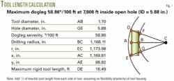
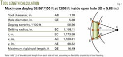
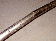
Tool-modeling software calculated a 16.5-ft maximum rigid tool length for this short-radius well (Fig. 1). The tool string, therefore, was configured and modified with knuckle joints to ensure no single component in the string exceeded the maximum rigid tool length (Fig. 2).
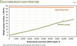
Modeling also indicated that 1.75-in. coiled tubing could reach the 9,315-ft TD. Fig. 3 shows the weight indicator readings for that depth. As shown, weight gauge predictions during pulling-out-of-hole do not exceed the operating limits.
Another factor modeled was the tool string configuration and well geometry. This modeling determined the maximum force applied to the tool string when entering the horizontal section. The maximum pickup force at 9,315 ft based on 50% of breaking strength was 2,346 lb.
Bending moment tests on the tool string determined its flexibility.
These analyses indicated that the job was feasible and had no greater risk than a standard horizontal coiled-tubing logging operation.
Logging tools
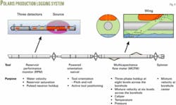
The Polaris logging tool contains two instruments: the RPM (reservoir performance monitor) and the MCFM (multicapacitance flowmeter).2 Additionally, the tool has a spinner flow meter mounted at the end of the tool string on the tool axis (Fig. 4).
The RPM is the latest generation of pulsed-neutron instruments for use in both vertical and horizontal wells. In determining the flow profile in deviated or horizontal wells, the RPM hydrolog provides an independent measurement of water velocity.
The MCFM has the latest multiphase-flow measurement technology. The meter combines conductance and capacitance instruments for distinguishing among three fluid phases: oil, water, and gas. Its output provides holdup, velocity, and three-phase inflow profiles.
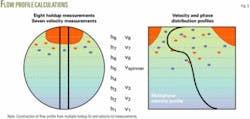
Processing and interpretation of the data from the tools provide a flow profile that is derived by combining individual fluid holdups from the MCFM with the individual velocities from the MCFM, the spinner velocity, and the RPM hydrolog water velocity. Fig. 5 illustrates the process.
Based on velocity and the holdup profiles, the analysis calculates average values for eight levels that are vertical to the wellbore. These values are then combined with the cross-sectional area at the given level to derive the flow rates at each level.
The analysis then combines all eight levels to yield flow rates for the fluids (water, oil, and gas) that then can be converted to surface conditions.
Logging operations
A dummy run prior to running the modified tool string in the hole determined the feasibility of the job. The dummy tools had a rigid tool length equal to the actual production-logging tool. A 1.75-in. coiled-tubing string conveyed the dummy tools through the high well dogleg without problems. Subsequent logging runs with the modified Polaris tool did not require excessive force on the tool string.
The program acquired a complete MCFM dataset, including flowing and shut-in passes, and MCFM station readings.
In addition to the MCFM data, the program recorded RPM hydrolog and PNHI (pulsed-neutron holdup imager) data as backup to MCFM holdup measurements.
Also the collected spinner data supported the velocity profile from the MCFM and RPM hydrolog readings.
Log interpretation
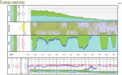
The evaluation derived the combined holdup during flowing conditions (Track 2 in Fig. 6) from the calculated holdups for the individual MCFM sensor rows. Well trajectory mainly controls the holdups. The profile shows six local traps that hold back the oil and change the holdup as well as the velocity distribution.
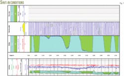
The holdup profile recorded with the well shut-in supports the statement that the trajectory rather than flow controls the holdup (Fig. 7). The water sumps and oil traps are in almost the same positions as with the well flowing.
Track 3 in Figs. 6 and 7 shows the velocity distribution across the wellbore built from the six MCFM correlations and the spinner velocity for flowing and shut-in conditions, respectively. Locations where the fluids are mixed have a strong sensor velocity correlation.
Observed in the track is a general velocity increase starting from the toe of the well. The highest velocities are at places where the holdup change forces one fluid to flow much faster than the other, such as:
• When the water is on the low side and the oil holdup is large.
• When the oil is on the high side and the water holdup is large.
The job recorded two complete RPM passes in the hydrolog mode, one for flowing and one for shut-in. Also the logging involved recording repeat passes with faster logging speeds across the intervals with higher water velocity. Additionally, the job recorded eight stationary measurements, six during flowing and two during shut-in.
Under flowing conditions, the hydrolog shows significant water flow starting from the end of the logged interval. Velocity varies with changes in holdup but shows an increasing trend in general. Near the top of the logged interval, the velocity of the flow reached values that were greater than the maximum practical logging speed. The log acquired during shut-in shows no water flow in the upward direction.
Like the MCFM, the spinner flow meter data also show upwards directed flow with steadily increasing values. Using the flowing spinner calibration passes, the analysis calculated a total fluid flow in the tubing (7,300-7,400 ft) as 3,540 b/d under downhole conditions.
The analysis used a 0.83 velocity-correction factor and took into account the volume occupied by the tool.
Spinner log evaluation in horizontal wells often is inconclusive because the spinner does not clearly define the type of fluid measured. The evaluation cannot easily convert velocity to flow rates, and therefore, one needs to treat spinner flow rates with caution.
Flow profile
Based on the acquired data and the described processing and interpretation, the evaluation generated a flow profile (Track 4 in Fig. 6) that shows the well having mostly stratified-wavy flow.
The well’s trajectory mainly controls the holdup, as seen from the combined holdup and wellbore geometry image in Track 1.
Oil and water flow starts from the end of the logged interval. The flow remains almost constant until about 8,890 ft. From there, the flow rate increases slightly, indicating some contribution from this section. The main oil and water flow comes from the interval 8,700-8,100 ft.
During the shut in, the logs did not indicate any obvious cross flow (Fig. 7).
Table 1 summarizes the flow rates under downhole conditions.
Well path
A postjob geological evaluation confirmed the well path location in the Arab-D formation. A full suite of openhole logs, including a gamma-ray log, were recorded when the vertical mother bore of the short radius horizontal was drilled in 1992. Subsequently, no logs were obtained when the vertical well was sidetracked in 1998 with a short-radius horizontal because of LWD and wireline tool dimension limitations.
The production logging operations discussed in this article did provide another gamma-ray log.
Forward modeling using geosteering techniques constrained and quantified the stratigraphic position of the horizontal sidetrack. This modeling used an in-house geosteering software in GOCAD which used the 3D geological model. Fig. 8 shows the results.
With the bottom of Zone 1 at 8,700 ft, Zone 1 contributed 69% of the flow while the remaining 31% is produced from Zone 2A (Table 1).
Pressure transient test
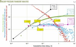
Prior to production logging, a pressure transient buildup test indicated that the well is completed in a low-permeability zone with a low productivity index. The derivative analysis of the buildup test identified the wellbore storage, first radial flow, linear flow, and the final radial flow associated with the horizontal-well pressure transient response (Fig. 9). This confirmed an effective 1,350-ft drainage radius.
The buildup test also suggests that the well is in a low-quality reservoir with the transient seeing the better reservoir through the low-permeability layer.
Future applications
Besides the results for this well, this modification has many applications and benefits for short-radius horizontal wells, in general. Currently, many of these wells have never been logged because of tool limitations. This application is a breakthrough in logging operations that enables one to determine the well’s effective production length, water entry, and zonal contribution to ensure a maximum oil seeep efficiency.
Acknowledgments
The authors are grateful to the Saudi Aramco management for their support and permission to publish this article. ✦
References
1. Sufi, A.W., Kumazaki, Y. and Haq, S.A.: “Production Logging in Multi-Lateral Wells - Interpretation, Problems and Solutions,” Abu Dhabi International Petroleum Exhibition and Conference, Abu Dhabi, Nov. 11-14, 1998.
2. Chace, D., Trcka, D., Georgi, D., Wang, J., Bousche, O., van der Spek, A., and Al-Nasser, H.: “New Instrument and Methods for Production Logging in Multiphase Horizontal Wells,” Middle East Oil Show and Conference, Bahrain, Feb. 20-23, 1999.
The authors
Oscar Kelder is a petrophysicist for Saudi Aramco in Dhahran. Previously he worked with Statoil ASA and Aker Geo Petroleum Services in Norway. Kelder has an MS in petroleum engineering and a PhD in petrophysics from Delft University of Technology, Netherlands.
Shaizad A. Chatriwala is a senior production engineer for Saudi Aramco in the Shedgum field-North Ghawar. He previous worked for Chevron Corp. Chatriwala has a BS in natural gas engineering from Texas A&M University.
Shouxiang Mark Ma is a petrophysicist in the reservoir description division of Saudi Aramco in Dhahran. Ma has a PhD from New Mexico Tech.
Fowzi Al-Shammari is a production engineer for Saudi Aramco in the southern area oil operation department, Abqaia. Al-Shammari has a BS in petroleum engineering from King Fahd University of Petroleum & Minerals, Dhahran.
Jerry P. Fontanilla is a petroleum-engineering specialist in the reservoir management division of Saudi Aramco, Dhahran. Fontanilla has an MS from the University of Calgary.
Abdullah Al-Towijri is a petrophysicist in the reservoir description division of Saudi Aramco, Dhahran. Al-Towijri has BS in petroleum engineering from King Saud University, Riyadh and an MS in petroleum engineering from Heriot Watt University, Edinburgh.
Bader A. Shammari is a petroleum-engineering specialist with Saudi Aramco in the upstream ventures department in Dhahran. Shammari is a graduate of the University of Kansas.
Andrew K. Murray formerly worked with Baker Atlas in Saudi Arabia.
Ulrich Herz is a senior petrophysicist with Baker Atlas in Dhahran. He has worked as a geologist and petrophysicist for various German oil companies. Herz has an MS in geology from Gubkin Institute for Oil and Gas, Moscow.
