Japan drills, logs gas hydrate wells in the Nankai Trough
Hideaki Takahashi
Japan Petroleum Exploration Co. Ltd.
Tokyo
Yoshihiro Tsuji
Japan Oil, Gas and Metals National Corp.
Chiba City
The Japanese continue to evaluate natural methane hydrates in the Nankai trough, drilling 32 wells through bottom-simulating reflectors (BSRs) during a 2004 research program.
The first part of this series (OGJ, Sept. 5, 2005, p. 48) introduced the general operations program for the Nankai trough, including logging while drilling, wireline logging, and coring activities. This concluding article details the experimental drilling program, the borehole temperature sensing program, and drilling and operational issues encountered in the Nankai Trough, Japan.
Experimental program
The purpose of the experimental program was to obtain engineering data and to verify technologies that could be used for future production. To test or develop hydrates in future, it was supposed that:
• The hydrate zone should be cased off and isolated completely by cementing.
• The hydrate zone should be drilled horizontally for more economical production.
Successfully cementing casing in extremely unconsolidated sediments requires that the hole not be severely enlarged. Inhibitive drilling fluids proved to be effective in preventing hole enlargement. The effectiveness of drilling fluids in stabilizing and cleaning the hole was indicated by borehole caliper and bottomhole pressure measured while drilling.
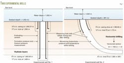
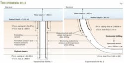
Obtaining formation pressure and fracture pressure measurements around the hydrate zone provides critical information for engineering calculations. To understand the difficulty or ease of horizontal drilling in the hydrate zone, the team conducted drilling trials (Fig. 1).
Two wells, one vertical and one horizontal, were drilled in 17.5 days after completion of the hydrate evaluation program. The experimental program was conducted by Japan Drilling Co. Ltd. (JDC), under contract to Japan Oil, Gas, and Metals National Corp. JOGMEC provided planning and analyzed the data after they were acquired. Japan Petroleum Exploration Co. Ltd. (JAPEX) assisted with operations.
Evaluating cement
In the 1999-2000 program, the surface casing was not sufficiently cemented and allowed some gas to migrate outside the casing, up to the seabed, when drilling the deeper, hot zone.
In the 2004 program, the condition of cement behind casing was evaluated with Schlumberger’s wireline acoustic tool combination CBL-VDL-USIT-GR (cement bond log, variable density log, ultrasonic imager tool, gamma ray). The tool was run into 95⁄8-in. casing, which was cemented in 121⁄4-in. hole of the first experimental well. To evaluate the well properly, the JDC allowed the cement to cure for 10 days before running the cement bond log. During the curing time, JDC drilled the second experimental well. The cement slurry used between the 95⁄8-in. casing and 121⁄4-in. hole was Halliburton’s tuned light cement system with 1.37 sp gr, which created less heat from hydration.
The log indicated good bonding that was sufficient to prevent gas migration. However, the continuity of the cement was not perfect.
Hole caliper measurement
The hole caliper was measured while drilling the 121⁄4-in. holes in both wells and the 81⁄2-in. hole in the horizontal well, with Baker Hughes INTEQ’s optimized rotational density (ORD) acoustic caliper sensor, located at 17 m above the bit.
After the hole was drilled and the bit was pulled into the casing shoe, JDC measured the hole again while running back to the bottom in order to get a time-elapsed log. To minimize hole enlargement, JDC drilled the first 121⁄4-in. hole while pumping slugs of 6% potassium chloride polymer mud occasionally between seawater.
Crews drilled the second 121⁄4-in. hole while pumping 5% sepiolite mud slugs occasionally between seawater and drilled the 81⁄2-in. hole, including the horizontal section, while pumping 5% sepiolite mud continuously without pumping any seawater. (Sepiolite is a clay mineral with a needle-like structure, similar to attapulgite, used to increase mud viscosity.)
On the log obtained during drilling of the first well with 121⁄4-in. bit, the caliper log of the hydrate-rich layers indicated a hole diameter less than 12.5 in., but that of the hydrate-less silty layers was around 13 in., and the hole diameter of the hydrate-less sandy layers was 14-15 in.
On the time-elapsed log, obtained after 20 hr of drilling, the hole diameter of hydrate-rich layers was 12.5-13 in., while that of the hydrate-less silt was 13.5-15 in., and the diameter of most of hydrate-less sand section was more than 15 in. Nearly the same tendency was observed on the caliper log of the 81⁄2-in. horizontal hole.
Formation, fracture pressure
To measure formation pressure and fracture pressure, engineers ran Schlumberger’s wireline cased hole dynamic tester (CHDT) into the 95⁄8-in. casing of the first experimental well. The tool has a 6-in. long, 0.281-in. diameter drill, which penetrates casing pipe and extends into the formation. An adjustable rate pump inside the tool is operated from the surface, able to either discharge or suction through the drill while the pressure is monitored.
The CHDT tool was run following the cement evaluation logging. Four measuring points were selected in and around the hydrate zone where cement bonding was identified as excellent. Each point was measured for several hours and a series of pressure charts was obtained, which is currently under analysis.
Monitoring BHP, temperature
BHI’s modular advanced downhole pressure measurement tool (MAP) was incorporated into the drill strings at both experimental wells. It transmitted the downhole pressure data to surface in real time while drilling. The pressure was supposed to indicate the hole condition, including such things as insufficient cuttings removal, hole collapse, and influx or lost circulation at depth.
This tool was supposed to tell what was actually happening in the hole, especially when any abnormal drilling parameter was observed at surface. As a result, at all times during drilling of the two wells, the hole condition was stable with no abnormal pressure downhole nor abnormal drilling parameters observed at the surface.
Downhole temperature data were also transmitted in real time from the MWD (measurement while drilling) tool. The data indicated that the temperature was always low enough not to dissociate the hydrate in the sediment while drilling.
Horizontal drilling
Horizontal drilling is a common practice in oil and gas exploration, but no operator has ever horizontally drilled such an unconsolidated shallow formation in deep water. A goal of one experiment was to drill 100 m horizontally in the hydrate zone, approximately 300-350 m below the seabed, in a water depth of 991 m.
To achieve this goal with the least difficulty, JDC set 95⁄8-in. intermediate casing halfway, where the hole angle was 12°, and 81⁄2-in. hole was drilled while pumping 5% sepiolite mud continuously without pumping any seawater. Sepiolite mud was used because it is prepared with seawater and does not require fresh water.
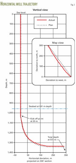
The well was kicked off 20 m below the seabed and the angle was built up with BHI’s mud motor with a bent housing adjusted at 1.5-1.8°. The bottom hole angle and azimuth data were transmitted to surface constantly while drilling, as well as other data such as hole caliper, pressure, temperature, formation resistivity, and gamma ray.
The actual well trajectory closely traced the planned course (Fig. 2). The hole angle reached 90° at 472 m from the seabed and remained at 90° until it reached the end of the hole at 572 m below the seabed.
According to the resistivity data while drilling, the well reached the hydrate zone at 255 m below the seabed because of the updip location. The wellbore was drilled another 317 m until it reached TD within the hydrate zone, which had a vertical thickness of about 50 m. There was no extra overpull or torque on the drill pipe. The goal of 100 m horizontal drilling was achieved easily.
BHT sensing program
The purpose of the high accuracy borehole temperature-sensing program was to obtain the precise temperature profile from the seabed to below the hydrate zone. The data obtained over a long period were supposed to represent the in situ formation temperature profile, which may indicate the theoretical phase boundary of the hydrate bearing zone.
The temperature is measured by a fiber optic sensor cable; one measures the distributed temperature and the other measures point temperature. The former technology provides continuous temperature profile over the zone where the fiber optic cable is located, with target performance of 0.1° C. resolution and 1.0° C. accuracy. The latter technology provides point measurement with better target performance of 0.01° C. resolution and 0.1° C. accuracy.
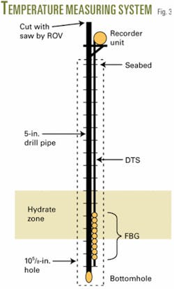
The fiber optic cable was deployed from the seabed down to approximately 100 m below the bottom of the hydrate zone, and the point measurement sensors were arranged at 31 points across the bottom of the hydrate zone, with 1-m spacing.
The temperature data from both systems were stored at a programmed sampling rate in the recorder, which was located above the seabed. The data were transferred to a PC when the recorder was retrieved at the end of the whole program.
The BHT systems were run in two LWD-logged wells following the respective wireline logging operation at the adjacent wells. The procedure was as follows:
1. Fiber optic cable was installed outside of 5-in. drill pipe with specially designed standoffs at every tool joint when the drill pipe was being run.
2. When the whole length of drill pipe with the cable was run from the drillship, the data recorder was mounted on the drill pipe with a support frame and was function tested before running it into water.
3. The system was run into the hole until the end of the pipe reached bottom, at which point the recorder would be located a few meters above the seabed.
4. The drill pipe was cut a few meters above the recorder with a diamond chain saw operated by ROV. The drill pipe was pulled out above the cut.
5. The measurement system was left for 2 months, recording temperature data at programmed sampling rates, typically twice a day, while other drilling operations were conducted at other locations.
6. When the program was finished, the drillship returned to retrieve the recorder. Engineers ran an overshot with drill pipe. The overshot connected over the cut pipe above the recorder with the assistance of an ROV.
7. The wireline colliding tool was run inside the drill pipe from surface and shot the explosive at approximately 70 m below the seabed to sever the drill pipe and the cable.
8. The severed pipe end was pulled up to 30 m below the seabed, and cement was pumped to fill the surface hole per regulations for abandoning a well.
9. The drill pipe was pulled out and the recorder was recovered. The 5-in. drill pipe and fiber optic cable below the severed point was abandoned in the hole.
This procedure worked successfully at the second well but failed at the first trial. At the first well, the system could not reach the planned depth of the hole and had to be pulled out then rerun after the hole was reamed. When the system was re-run, it could reach to the bottom, but the recorder was seriously damaged due to interference with the seabed during a depth positioning operation. Thus, no data were recorded.
But, at the second well, the procedure went smoothly without any problems, and temperature data from all depth were successfully obtained over a 51-day period (the system was deployed on Mar. 25, 2004, and the recorder was retrieved on May 14, 2004). Fig. 3 shows a schematic of the system.
This high-accuracy borehole temperature-sensing program was performed by Schlumberger K.K. under contract with JOGMEC, including developing the equipment and interpreting the data obtained. Operations were carried out in conjunction with JAPEX.
Drilling, operational issues
Gas flow at seabed
Gas flow from holes being drilled, cored, or logged was always monitored by a remotely operated vehicle (ROV). When the drill pipe was rotating, the ROV stayed approximately 10 m off the well at the seabed. The ROV kept the same azimuth from the drill pipe to the ROV cable on the drillship to avoid becoming entangled.
Because of the distance and poor visibility when circulating mud, the ROV’s sonar was used for distinguishing gas bubbles. The results of simulation tests carried out in the 1999-2000 program were used to gauge the severity of the gas on the sonar image. The earlier tests had recorded the sonar image of stepwise regulated air bubbles in 20 m water.
The safety procedure in the event of a strong continuous gas flow was thoroughly discussed in advance among all key crews on the drillship. A 90 cu m slug of weighted kill mud (1.5 sp gr) was always kept agitating in two of the six mud pits, ready to be pumped down. The ROV monitored the wells especially carefully when drilling through the BSR horizon at the first well in each location, (inevitably it was always an LWD well).
During the whole program, indications of weak gas bubbles on the ROV sonar image were observed at two LWD wells when they drilled below the BSR horizon. Each indication on the sonar disappeared within a minute.
After those wells were drilled to their total depths, the ROV approached the well and visually observed the hole with TV cameras with the drill pipe rotation and circulation stopped, and confirmed no gas bubbles in the static condition. The weighted kill mud in the pits had never been pumped to the end of the whole program.
ROV subsea operations
Throughout the program, the ROV significantly assisted each subsea operation by:
• Monitoring gas flow.
• Monitoring that the pipe was actually moving down while tripping in hole. (the drill pipe bent severely in the 1999-2000 program without this confirmation.)
• Guiding the drill bit to the correct coordinate at the seabed and re-entering the pipe end into the hole.
• Confirming the absence of any submarine cable before the bit touched down.
• Monitoring the condition of the wellhead systems of the experimental wells.
• Cutting and connecting the borehole temperature-sensing system from and to the running string.
• Confirming cement return when plugging and abandoning all wells.
The caged type Magnum 88 (100 hp) ROV from Oceaneering International Inc. was installed on the JOIDES Resolution after 10-days extensive welding work at Galveston before the drillship was mobilized to Japan. During the 106-day operation offshore Japan (excluding days for port calls), the ROV was in the water for a total of 1,493 hr, which was several times longer than normal riser drilling operations for oil and gas exploration.
The total mechanical downtime was 87 hr, most of which was due to electrical problems. The ROV crew repaired each in several hours. The ROV was dismantled at Gamagori before the drillship was demobilized back to the US.
Well abandonment
All wells were plugged and abandoned by placement of a 30-m cement column below the seabed as required by Japanese mining regulations.
For LWD wells, as cement was not allowed to be pumped through the delicate LWD tools, an open-end drill pipe was run into the LWD-logged hole down to 50 m below the seabed to spot a high-viscosity gel mud that was supposed to support the heavy cement slurry on it. Then the pipe was pulled up to 30 m below the seabed to pump cement slurry, while the LWD tools were at surface to transfer data from memory to the PC, and to change out the radioactive source and the batteries for the following LWD well.
For cored holes, workers pumped cement slurry through the core bit after the inner barrel was retrieved by wireline. Then, the core bit was pulled out above the seabed and flushed with seawater at an extremely high pump rate. When moving to the next coring location, the coring assembly was kept hanging from the drillship, if the distance was less than 10 miles and if the sea was calm.
For wireline-logged holes, cement was pumped through the 65⁄8-in. drill pipe, which was used as the logging riser at the end of all logging runs. The two experimental wells were plugged with cement after casing pipe was cut a few meters below the seabed. The two wells used for the borehole temperature sensing were plugged by pumping cement through the severed end of the drill pipe before pulling the recording unit to the surface.
Drilling fluids
During drilling with LWD and coring, seawater was pumped down the hole, but as a routine precaution to keep the hole in good condition, 5 to 8 cu m gel mud with specific gravity 1.15 was pumped down every 27 m of drill pipe connection when drilling, and after every a few meters of wireline core retrieving operation when coring. The holes were always stable, and no problems, such as a tight hole or stuck pipe, were experienced.
Wireline logging was run after the hole was displaced with 60 cu m of the same gel mud and quickly followed by drilling, pumping 5 cu m gel mud after every 27 m of pipe. All logging tools could run to the bottom without any problem and provided excellent logs at both wells. The experimental wells were drilled with potassium chloride mud and sepiolite mud, as described above.
As all pumped mud was dumped when it was circulated out to the seabed from the hole due to the riserless operations, supplying the total volume of mud materials required was a huge logistical challenge.
Logistics
The drillship, JOIDES Resolution, made six scheduled port calls for a total of 15 days during the 122-day program.
The first port call was made upon the drillship’s arrival in Japan at Gamagori, where all equipment and materials for the initial program were loaded including LWD and drill pipe. JAPEX and JNOC personnel were aboard the drillship with third-party crews. Another four port calls were made as scheduled to change out equipment on the limited deck space and to load consumable materials that were limited by the tank capacity.
The last (sixth) port call was made at Gamagori before the drillship returned to the US from Japan, during which all equipment used for the program was offloaded, including the ROV.
The program was planned to minimize the number of port calls. Completing each port call effectively in minimum number of days required that all equipment and materials to be loaded be prepared at the port before the drillship’s arrival. For example, 22 tons of potassium chloride for the mud of the experimental wells were mixed to 88 cu m fluid in tanks which were temporarily set up at the jetty, then pumped out to the mud pits on the drillship at the fifth port call in a diluted state, instead of loading a huge number of pallets of sacks.
A 13-passenger helicopter was chartered for transporting personnel between the base at Gamagori and the drillship offshore. The helicopter made 64 round trip flights, carrying a total of 623 passengers during the program. This helicopter also made crew changes for the drillship on fixed dates when the drillship was offshore.
Overview
1. Based on all technologies verified in the 1999-2000 program at a single location, the data for the evaluation of the hydrate occurrence of extensive area in the Nankai Trough were collected in the 2004 program by drilling 32 wells at 16 locations where various types of BSR and velocity anomaly had been observed on the 2D and 3D seismic sections.
2. Each of 16 locations was first drilled with LWD. Two locations were drilled and wireline-logged to supplement LWD logs. Log quality was excellent and each log identified the general occurrence of hydrate at the location, which verified the seismic interpretation.
3. A total of 600 m of core samples was recovered from 12 wells at four locations. The pressure-temperature core sampler retrieved 161 m of high-quality core samples at 79% recovery. The PTCS tools and core-handling procedure were greatly improved from those used during the 1999-2000 program. All core samples were sent to laboratories for detailed assessment studies to ascertain resource volume, productivity, and environment.
4. The experimental programs were conducted in two wells, including evaluations of casing cementing, hole caliper measurement, formation pressure and fracture pressure measurement, bottomhole pressure and temperature monitoring, and horizontal drilling. Each experiment provided valuable engineering information for future testing and development. It turned out to be easy to drill 100 m horizontally in the hydrate zone in deep water.
5. The high-accuracy temperature profile from the seabed to below the hydrate zone was recorded over a 51-day period by deployment of optical fiber temperature measurement systems in a well. The data obtained were good quality. Although another set of the fiber optic systems was deployed at another location, data were not recorded due to the recorder damage.
6. No shallow gas hazard was experienced at any of the 16 well locations.
7. All scheduled programs were successfully performed in 122 days, just under the planned 123 days. The dynamically positioned drillship equipped with ROV was well suited for the multiwell exploration program in the extensive deepwater area.
Ongoing and future programs
METI established the Research Consortium for Methane Hydrate Resources in Japan1 (MH21 Research Consortium) in 2001, under which all on-going and future programs are conducted toward the goal for the next decade, based on accomplishments in the last decade.
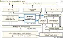
For evaluation of the resource potential of natural gas hydrates, the potential quantity, productivity, and environmental impact must be evaluated comprehensively. Fig. 4 shows a general schedule of Japanese hydrate evaluation program. A similar figure appeared in OTC Paper 130402 and OTC Paper 151243, explaining each process step. Fig. 4 summarized the 2004 multi-well exploration program.
Work currently underway includes:
• Interpretation of 2D and 3D seismic survey is being verified referring to the logs and core samples, which will significantly improve technology of predicting hydrate occurrence.
• Logs and core samples are being analyzed to quantify net volume of hydrate in the sediment, which will bring more practical estimate of resource quantity.
• Core samples are being analyzed not only for resource assessment but also for studies on production method and environment assessment, which will suggest some criteria for future development.
• Data obtained through the experimental program are being studied for design of the next offshore production test.
Acknowledgments
This program was achieved through the teamwork of METI (promotion and funding), JNOC (planning), JAPEX (operations), and many contractors. Especially, Transocean’s crew on the JOIDES Resolution performed every new operation smoothly and safely. Oceaneering’s crew made 87 ROV dives totaling 1,493 hr, significantly assisting all operations.
Jim Aumann of Aumann Associates Inc. has finally completed the PTCS with his continuous effort since 1996. Schlumberger K.K. in Japan undertook the high accuracy bore hole temperature-sensing program, developing a new, original device in. JDC successfully applied the latest technologies of the oil and gas industry to the experiment program. In addition, the authors thank all persons who were involved in the 1999-2000 program because the success of the 2004 program was based on their achievements.
Finally, the authors acknowledge the Steering Committee of the MH21 Research Consortium and METI, who kindly granted permission to publish this article.
References
1. www.mh21japan.gr.jp/english/index.html.
2. Takahashi, H., Yonezawa, T., and Takedomi, Y., “Exploration for Natural Hydrates in Nankai-Trough Wells Offshore Japan,” Offshore Technology Conference, Houston, Apr. 30-May 3, 2001.
3. Takahashi, H., Yonezawa, T., and Fercho, E., “Operation Overview of the 2002 Mallik Gas Hydrate Production Research Well Program at the Mackenzie Delta in the Canadian Arctic,” Offshore Technology Conference, May 5-8, 2003.
