Flare minimization practices improve olefins plant start-ups, shutdowns
Lyondell Chemical Co. is implementing flare minimization processes at all its olefins plants to reduce emissions and minimize effects on the surrounding community.
Lyondell’s Channelview, Tex., complex significantly reduced emissions during separate turnarounds for the site’s two olefins plants in 2003. Lessons learned from the first turnaround were incorporated into the second turnaround.
In 2004, the Corpus Christi, Tex., complex reduced emissions significantly when it applied the Channelview experiences to a different olefins process.
For years olefins plants have flared off-specification products during shutdowns and start-ups for maintenance turnarounds. During shutdowns, companies historically reduced feed and flared off all products until the plant was de-inventoried. During start-ups, companies would flare the products until pipeline specifications were met.
This article discusses the Lyondell approach to reducing turnaround emissions in the Channelview and Corpus Christi facilities and the approach used to minimize turnaround emissions in all eight Lyondell olefins facilities. Olefins plants throughout the world can use these methods to reduce emissions.
Olefins plants
In the past, olefins units were started up with large volumes of feedstock to satisfy minimum flow rates for downstream equipment and to facilitate the production of hydrogen, methane, and high-pressure steam, which is required to get the olefins products on spec.
Over the years, the Lyondell philosophy has changed to one of minimal flaring to mitigate potential concerns with the surrounding community and become more environmentally friendly. Many of these concerns-such as noise, a large flame, dark smoke, vibration, light, and emissions-were associated with the operation of the olefins flare during start-ups, shutdowns, and upset conditions.
In addition to public concerns, tighter environmental regulations as well as an economic incentive to reduce flaring have necessitated a change in how olefins plants operate. Episodic events, such as plant start-ups and shutdowns, cause emissions and increase costs, which leads to a huge incentive to minimize flaring during these events.
With flare minimization and emissions reduction becoming a high priority for all, the question now being asked is how this will be accomplished. This article addresses how to reduce flaring and emissions and presents solutions that have had favorable results during start-ups and shutdowns.
Ethylene plant
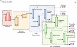
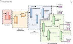
Fig. 1 shows the basic processes in an ethylene production plant.
Ethylene is produced via the pyrolysis of hydrocarbons at very low pressures and high temperatures in a cracking furnace. The reaction yields a mixture of hydrocarbons including, but not limited to hydrogen, methane, ethane, ethylene, propane, propylene, butanes, pentanes, gasoline, and aromatic products.
The mixture from the furnace is initially cooled to separate the gasoline and aromatic hydrocarbons from the C4 and lighter products. This is done in the quench area of the plant at low pressure. The recovery of lighter-end components-hydrogen, methane, ethylene, and propylene-requires high pressures and low temperatures for the separation.
Effluent from the quench area is compressed in a multistage compressor to more than 500 psig and then chilled to very low temperatures with ethylene and propylene refrigeration. This part of the process yields hydrogen, methane, ethylene, and propylene products with a conventional distillation. Additionally, process contaminants are removed via fixed-bed reactors. If not removed, these contaminants would result in the ethylene and propylene products being off specification.
The on-spec ethylene and propylene are sent to customers via pipelines. Most olefins units do not typically have storage capability for off-spec ethylene or propylene. Any off-spec product must be flared until it meets customer specification.
Lyondell olefins
The two nearly identical olefins units at the Channelview complex were designed by Lummus Engineering (now ABB Lummus Global) and first began sustained ethylene production in 1976. A major debottleneck project in 1989 and a smaller expansion project in 1995 increased the units’ production of ethylene and propylene.
The Corpus Christi complex was designed by Stone & Webster Engineering Co. and began ethylene production in 1980. The plant was originally designed to produce ethylene from a mixture of naphtha and gas oil. The plant was later modified to increase its flexibility to feed LPG and to expand its ethylene and propylene production capacity.
Decontamination process
Turnarounds, executed in Channelview in 2003 and Corpus Christi in 2004, were the first turnarounds for these olefins units since 1996. Stricter environmental and personnel exposure standards required improvement in some of the clearing techniques and procedures used to prepare various portions of the plant for maintenance during previous turnarounds.
The proximity of the two olefins units at Channelview allowed us to de-inventory some of the light-end products to the olefins unit that was still operating. Although this is somewhat unique to the Channelview complex, there are still opportunities for single-site facilities, as demonstrated at the Corpus Christi complex, to use this shutdown decontamination method.
Traditionally, the charge-gas compressor system and flare system would set the critical path schedule for our maintenance turnarounds; therefore, we emphasized these areas to turn these systems over to maintenance safely and quickly. This process allowed operations to clear this area of the plant and turn it over to maintenance in the shortest time.
We established a team to determine methods for minimizing flaring during start-up and shutdown. The team found that a methane sweep helped free benzene from the charge-gas systems.
After reviewing the performance curves of our process-gas compressor, we determined that it could not compress methane due to its molecular weight but could compress ethane gas under certain conditions. If the discharge pressure of the machine could be kept low enough, we could operate the compressor without surge even though ethane gas has a lower molecular weight than our typical charge gas.
This information allowed us to develop a method that uses the charge-gas compressor to circulate ethane gas along with propylene, butanes, and pentanes through most of the plant. Once ethane-gas circulation has been established, the intent is to purge the residual benzene and butadiene from the circulating system.
We initially used this decontamination procedure for the first olefins turnaround in early 2003, but it had limited effectiveness because the molecular weight of the material going through the charge-gas compressor was heavier than during normal operations. This caused large quantities of the process gas to condense in the compressor train, which resulted in a premature shutdown of the process because the system could not remove these condensed liquids from the compressor train.
We used a process simulator to model the compressor train to determine the proper mix of hydrogen, methane, ethane, propylene, butanes, and pentanes required to prevent this inventory of liquids in the compressor train. As a result of this study, we made piping modifications and upgraded procedures to allow the hydrogen and methane recirculation to approach actual operating conditions of the compressor train more closely. This would therefore eliminate the problems from large quantities of condensed liquids in the compressor train.
This new ethane-sweep procedure was used for the shutdown of the other olefins unit later in 2003.
The decontamination and shutdown procedure uses existing piping (with some short jumper lines) in the unit to recycle the previously mentioned products back to a furnace, the quench area, or the charge-gas compressor suction. This is the lineup used in the ethane sweep and decontamination procedure:
• One cracking furnace on a butane-pentane mix, which is free of butadiene.
• Two cracking furnaces on ethane recycle or purchased ethane.
• Hydrogen, methane, and propylene recycle supplied to the charge-gas compressor suction to maintain the correct molecular weight.
• Heavy pyrolysis gasoline (benzene free) routed to the quench area.
This combination of hydrocarbons is the right “mix” that provides adequate decontamination of both the light-ends part of the process as well as the heavier-end, which contains benzene and butadiene.
Before shutting down the unit, one should make the normal preparations that reduce inventories in tanks, towers, exchangers, drums, etc., to minimize the amount of material that has to be flared. Also, the products that will be used in the decontamination process should be available in inventory.
As cracking furnaces are taken offline during the shutdown, the three decontamination furnaces (coil outlet temperatures below cracking temperature) are brought online along with the hydrogen, methane, and propylene recycle flows. These decontamination rates are increased as the furnace feed rates are reduced to maintain a constant flow rate to the charge-gas compressor.
Heavy pyrolysis gasoline feeds the quench area to help purge the heavier hydrocarbon streams of benzene. This gasoline stream, along with the butanes and pentanes, is purged from the unit to storage tanks where it will be reprocessed at a later time.
Once the decontamination process starts, one should sample key points in the unit for butadiene and benzene. When the concentration of these components reaches the desired level, the decontamination process is stopped and unit de-inventory is started.
Decontamination benefits
The new techniques of the plant-wide ethane, propylene, butane, pentane, and heavy pyrolysis gasoline circulation helped minimize benzene and butadiene emissions and reduced employee potential exposure for benzene and butadiene.
Other benefits included:
• A lesser impact to the surrounding community in terms of noise and environmental effects.
• Benzene levels in equipment were reduced 99+% before the plant was shut down.
•The clearing time for critical-path equipment was 4 days quicker, which shortened the turnaround.
• Flaring was reduced 70% compared with previous shutdowns; flaring could be potentially reduced by 85-90%.
• Fewer feedstock and product losses.
Start-ups, past practices
The common method to start up an olefins plant is to bring up some of the cracking furnaces on import feeds and process forward to the next manufacturing step as they begin to produce on-spec products.
Furnace effluent, for example, is flared until the compressors are ready to receive this product from the furnaces. Once the compressors are brought online, the process gas is fed forward to the driers, chilling train, and then the distillation towers in the back end where ethylene and propylene are produced.
At each step in the process, the product is typically flared until the next step is ready to process it or until final product specifications are met in the ethylene and propylene distillation towers. Flaring ethylene and propylene can occur for 10-12 hr or longer until these products are on spec and in the pipeline.
Once the plant is producing on-spec products, additional furnaces are brought online and rates are increased.
Olefins manufacturing facilities have attempted to reduce flaring during start-ups by recycling back-end products-ethylene, propylene, etc.-to the cracking furnaces or charge-gas compressor.
Disadvantages with this strategy are unstable operations due to changing feed compositions to the charge-gas compressor as furnaces are brought online and low temperatures in a section of the plant that is not designed for them. This is a result of letting down light hydrocarbons from a high pressure (back end of unit) to a low pressure (furnaces or compressor suction).
Channelview olefins tailchase
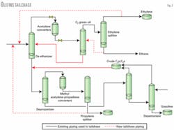
The tailchase method is actually simple. Existing piping and new piping recycle internal streams back to a single point (the de-ethanizer feed) to form a continuous processing loop in the plant’s back end.
The product distillation towers and refrigeration systems are started up with ethane, ethylene, propylene, butanes, and pentanes from product pipelines. Once the distillation columns are on spec and working properly, feedstock is introduced into the cracking furnaces at a low feed rate.
Furnace effluent is compressed and routed to the distillation columns that are already operating at conditions to produce on-spec products.
For our 2003 olefin turnarounds, we installed the following piping to allow the plant’s back end to operate in tailchase mode:
• Ethylene recycle from the ethylene product pumps to the de-ethanizer.
• Propylene recycle from the propylene product pumps to the de-ethanizer.
• Ethane recycle from the ethylene splitter to the ethylene green oil stripper and consequently to the de-ethanizer.
• Ethylene makeup to the system while tailchasing from the ethylene product pump.
This piping allows all the equipment downstream of the demethanizer-including the acetylene converters and methyl acetylene-propadiene converters, which can be a large contributor to flaring-to be on spec and waiting on furnace feed. When this is completed, the cracking furnaces can start processing feed.
Fig. 2 shows a simplified flow diagram of the olefins tailchase process.
Corpus Christi start-up
The Channelview successes were shared with the Corpus Christi complex, which led to similar shutdown and decontamination procedures.
We used the decontamination concept to develop start-up procedures that were different from Channelview but produced similar results. These changes, in addition to continual sharing of knowledge company-wide, led to significantly reduced flaring at Corpus Christi.
The method of starting up the Corpus Christi complex was somewhat different from the methods used in the Channelview complex due to availability of raw products for initial inventory and piping and equipment available.
The Corpus Christi start-up placed back-end towers on total reflux and started the quench compression and chilling train on total recycle. We manipulated the process gas composition by adjusting the amount of ethane, methane, hydrogen, and propane in the system to achieve the desired gas molecular weight and dewpoint.
The furnaces were slowly started on recycle; when the acetylene reactors were up to temperature the furnace feed and coil outlet temperatures were increased. Major steps in the process includes:
• Inventory and start-up of quench section.
• Inventory and place propylene and ethylene refrigeration system in service.
• Purge and inventory front end through chilling train, back-end towers.
• Back-end towers on total reflux.
• Recycle chilling train to compression (methane recycle).
• CO2 removal.
• Chill down.
• Recycle back-end products to the furnaces (C2s and C3s recycled).
• Add fresh feed to furnaces.
• Hydrogen to acetylene converters and increase furnace coil outlet temperatures.
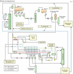
Starting the plant without a furnace feed required piping modifications to recycle material from the chilling train to the process-gas compressors; a method of handling CO2 from import methane and ethane; a good understanding of the steam plant balance; and correct gas composition to maintain compressor performance and prevent condensation in certain areas of the plant.
Much of the piping required to recycle streams from the chilling train to the process-gas compressor was available; only short sections of piping were required to tie the additional chilling streams and import methane to the recycle piping already present. We added a temporary ethane line to bring ethane from the furnace feed system to the process-gas compressor train upstream of the caustic tower.
We were in the process of installing propylene and ethylene vapor-inventory systems that would minimize autorefrigeration potential in various columns in the back end of the plant. These were used to inventory towers in the back end and start them on total reflux. Other piping for inventorying gasoline and butane were already available.
The import ethane and methane streams contained CO2, which could cause freezing problems in the cold train, as well as contamination of ethylene product if handled incorrectly. To deal with the CO2, we circulated the process gas stream through the caustic tower and chilling train before chilling down.
One of three process-gas driers was used during this stage of the start-up and we planned to swap driers once the plant came on stream. The molecular sieve lightly adsorbs some of the CO2, which is later displaced by water.
Fig. 3 shows the Corpus Christi olefins recycle start-up diagram.
Steam availability has caused difficulties with shutdowns and start-ups in the past. The Corpus Christi complex has abundant steam production since the addition of a cogeneration plant. Before the shutdown, we studied the steam balance carefully to minimize any steam users and we ran electric motors instead of steam turbines when it improved the steam balance.
We also maintained the boilers to ensure there would be no operating problems during the shutdown or start-up sequence. The steam balance was tight and could have caused a process delay if there were any upsets.
The process-gas composition was kept such that the molecular weight of gas through the compressor was close to the design specification. We also considered the gas dewpoint when determining the necessary system pressure to prevent condensation during the CO2-removal process. The pressure was later increased to allow condensation in the chilling train but not in the process-gas aftercoolers. The composition was monitored periodically throughout this process.
Tailchase benefits
The benefits for using the tailchase method for start-up include fewer emissions, lower costs, and lower impact on the community that surrounds the olefins unit. Major benefits for this process include:
• Minimal flaring associated with olefins unit start-ups and, therefore, less impact on the environment and neighboring community.
• The total pounds flared during start-up were reduced 75-80%.
• Less flaring of valuable feedstocks and products results in considerable cost savings.
• The verification of analyzers, instrumentation, and mechanical equipment before introducing feed to the furnaces.
• The operators could get a feel of operating the unit after an extended turnaround before importing feed into the unit.
• Most of the plant can be brought online at a controlled pace before the critical start-up activities associated with establishing feed to the furnaces.
In addition to using this process during a start-up after a turnaround, it also effectively reduces emissions during a unit restart from a planned charge-gas compressor or ethylene compressor outage.
Future work
This article has covered how three of the eight Lyondell olefins units have significantly reduced outage emissions. Each plant will be incorporating ideas learned from the previous outages to continually lower emissions.
Lyondell has many best-practice teams that share the best company ideas; one of these best-practice teams has been working on flare minimization for several years. Currently, many of the personnel involved with the Channelview and Corpus Christi improvements are working with the other five olefins plant-engineering groups to identify ways to reduce outage emissions.
The next site to have a major outage is the Clinton, Iowa, plant. Clinton has had some experience with flare minimization during outages, but will identify many new techniques from our collective experience.
Reducing flare emissions has had many positive effects. We are receiving significantly fewer complaints from our neighbors and more compliments from the communities. Flaring of costly feedstocks has been dramatically reduced. Overall turnaround costs have been reduced due to better and quicker decontaminations and better planned and executed start-ups. ✦
Based on a presentation to the National Petrochemical & Refiners Association Annual Meeting, San Francisco, Mar. 13-15, 2005.
The authors
David Chenevert ([email protected]) is the olefins technical superintendent for Lyondell Chemical Co.’s olefins manufacturing facility, Channelview, Tex. He has 14 years of manufacturing experience in the olefins industry and is responsible for the direction of the facility’s technical department. Chenevert holds a BS in Chemical Engineering from Louisiana Tech University.
Carl Harry is an olefins process specialist for Lyondell Chemical Co., Channelview, Tex. He has worked at the Channelview complex for more than 29 years with 22 years of those in the olefins units.
Jim H. Walker is an olefins process consultant and currently works in the olefins process engineering group at Lyondell Chemical Co.’s Channelview, Tex., chemical complex. He has 35 years’ experience in operations of olefins plants during normal operations, start-up, and shutdown conditions.
Byron Unterbrink is a production engineer at Lyondell Chemical Co.’s, Corpus Christi complex. He has worked at this plant for more than 8 years. Unterbrink has worked in the refining, olefins, and petrochemical industry for more than 13 years, providing technical support for a variety of process units. He holds a BS and MS in chemical engineering from Texas A&M, Kingsville.
Mike Cain is the plant manager at Lyondell Chemical Co.’s Corpus Christi complex. During his 33 year career, he has held various assignments at six different manufacturing facilities. Cain was previously a plant manager at Equistar Chemicals LP’s Lake Charles, La., and Beaumont, Tex., plants. He holds a BS in chemical engineering from the University of Oklahoma.


