Method determines valve automation for remote pipelines
An economical and technically feasible method is available for determining effective pipeline block valve automation for remote operations.
Most pipeline codes do not stipulate requirements for block valve spacing or remote pipeline valve operations along transmission pipelines carrying low-vapor-pressure petroleum products. This requirement is generally industry driven to control hazards and reduce environmental effects of pipeline ruptures or failures causing hydrocarbon spills.
This article summarizes pipeline codes for valve spacing and spill limitations in high consequence areas (HCAs). It also provides a criterion for an acceptable oil spill volume caused by pipeline leak or full rupture. The criterion is based on industry's best practice.
The application of the technique for deciding valve automation was applied to three pipelines in Brazil: Oleoduto RLAM-Sul da Bahia (ORSUB), Oleoduto Santa Catarina-Parana (OSPAR), and Oleoduto Rio-Belo Horizonte (ORBEL). These pipelines represent about 14% of the total liquid petroleum transmission lines operated by Petrobras Transporte SA. (Transpetro) in Brazil.
Results of the technique are provided here for two of the pipelines: OSPAR (117 km, 30 in.) and ORBEL II (358 km, 24 in.). Both carry large volumes of crude oil.
Pipeline advantages
Pipelines are usually the only feasible transportation for moving significant volumes of petroleum products over long distances. Records show that pipelines transport about 67% of petroleum products,1 yet pipeline spills have the least environmental impact.2
While pipelines have significantly better accident loss records (deaths, injuries, fires, explosions) than any other mode of transportation, they invoke greater awareness of safety-related incidents and issues and are closely watched by regulatory agencies, communities, and news media.
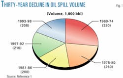
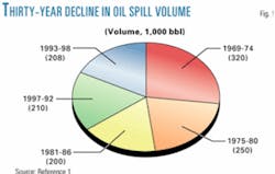
However, it is technological development and proactive actions by pipeline operating companies to increase safety and minimize environmental impact—along with corporate citizenship—that enable the industry to improve its pipeline transportation safety record. As a result, the annual volume of oil spilled has fallen by about 60% when comparing the 6-year periods 1969-74 and 1993-98 (Fig. 1).
The industry works in a number of ways to prevent oil spills, targeting the five leading causes of pipeline accidents:
- External third-party damage (caused by unauthorized excavation or external forces such as land slides).
- Corrosion.
- Pipe defects.
- Operator error.
- Operational failures.
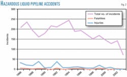
Pipeline companies face enormous expense and public relations consequences when pipeline failures cause spills. A proactive stance by industry has led to a steady decline of incidents since 1994 (Fig. 2).3
In Brazil, almost all oil, gas, and refined liquid products move through a network of about 15,320 km (9,500 miles) of onshore and offshore pipelines. These pipelines are owned and operated by Petroleo Brasileiro SA (Petrobras).
Petrobras Transporte SA (Transpetro) is the Petrobras subsidiary that operates 9,300 km (5,875 miles) of onshore pipeline networks, of which about 6,500 km (120 different lines with 8-42 in. OD) transport various high and low-vapor-pressure liquids and products including crude oil, diesel, LPG, gasoline, condensate, aviation, and other fuels.
About 17% of these pipelines are transfer lines serving plants, terminals, and other shipping or receiving locations. These lines ship more than 55% of the crude oil production and refined products.
In 2001, these pipelines transported more than 2.7 billion bbl of oil, or about 7.4 million b/d.
Transpetro-operated liquid pipelines traverse varying terrain. They pass through populated and ecologically sensitive areas—including high mountains, meandering rivers, and other waterways—and areas subject to geotechnical activity.
Although pipeline right-of-ways (ROW) were well planned and designed at the time of construction, some have been subject to unforeseen natural forces, such as landslides, that have resulted in pipeline ruptures. An example is the rupture of the 94.5 km, 12 in. Oleoducto Araucária-Paranaguá (OLAPA) pipeline—transporting light oil from the Paraná (REPAR) refinery at Araucária, state of Paraná, to Paranaguá marine terminal—in February 2000. This was caused by a deep-seated geotechnical slope movement.
Later review of the pipeline system indicated that it was designed and constructed to the requirements of the codes and regulations prevailing at the time. Nevertheless, Transpetro wanted to follow the cardinal rule of safety: "Prevention of spill necessarily requires a proactive approach, which anticipates the risks and initiates action to minimize those risks of oil spill."5
A comprehensive program was undertaken, therefore, to review all pipelines and assess the need for automating mainline block valves for remote operation to reduce spills in the event of pipeline leaks or ruptures.
Pipeline valve automation
Details of the above review are found elsewhere.6 These include valve placement and automation criteria, code requirements and industry practice, spill and leak considerations, and physical requirements for remote operation—including any interlock with the SCADA system.
Placement, automation criteria
Codes do not indicate a specific requirement for mainline block valve spacing. ASME ANSI B31.47 and DOT CFR 1958 differentiate between low and high vapor pressures (LVP and HVP) liquid pipeline transportation.
Mainline valve locations are decided on according to the appropriate section in transportation of LVP liquids. However, Canadian Standard code CSA Z662 specifies valve spacing of 15 km for HVP liquid lines in HCAs.9 ASMI ANSI B31.4 also requires valve spacing of 12 km for LPG and anhydrous ammonia lines in industrial, commercial, and residential areas. US DOT-CFR Part 195.248 defines major water crossings as those more than 30 m wide.8
Codes do not specify requirements for remote valve operation, except for ASME ANSI B31.4, which requires placement of remotely operated block valves at remotely controlled pipeline facilities.7 The pipeline industry worldwide generally follows applicable codes, but there is no uniform industry practice in valve spacing and valve automation. Pipeline companies take actions to have tools, equipment, and resources to respond to emergency situations to protect pipelines, the public, and the environment whether a system is automated or nonautomated to prevent or avert accidental spills.
Spill, leak considerations
Codes reviewed for acceptable limitation of leak volume included API 1130, API 1149, API 1160, and US Coast Guard Rule 33 Code of Federal Regulation (CFR) 155, Section 1050.10-13
US Coast Guard criteria adopted by US Department of Energy (US DOT), Office of Pipeline Safety (OPS), consider a total leak-rupture volume of 3,180 cu m for determining a section of a pipeline that will have the potential to affect an HCA. This is equivalent to a spill spread of about 400 m in diameter and 2.5-cm thick.
The worst-case scenario (full mainline rupture with 100% potential rupture volume out) is generally used for calculating the potential volume spilled in the event of a rupture. This is based on the following:
- Maximum capacity (throughput) of the pipe- line.
- Location of emergency flow restriction devices (EFRDs), such as remotely controlled valves and check valves.
- Pipeline ROW elevation and actual physical pipeline characteristics (diameter and wall thickness).
- Time to recognize rupture (i.e., time to isolate rupture).
- Initial loss and stabilization loss.
Generally, SCADA systems provide alarms for ruptures or leaks. Industry practice and experience show that such a system usually provides an alarm within 1 min of a full mainline rupture, followed by an additional 1 min to identify the rupture (usually by a pipeline operator).
This is followed by shutdown of the EFRD in about 3 min either by the operator or automatically in the case of a closed-loop system. Thus, the time to isolate a given rupture location is 8 min (5 min to recognize and initiate isolation plus 3 min for remote controlled valves to close).
The material balance leak-detection system is generally used for leak detection by most liquid pipeline companies that run on 5-min cycles; thus, no more than 5 min will elapse between a rupture being recognized by leak detection and the initiation of shutdown. The leak-detection system is a backup to operator recognition of a rupture.
Leak volume calculations are based on initial loss and stabilization loss:
- Minimum Initial Loss.
- Initial Loss = Time to Isolate the Rupture Point (i.e., 8 min).3.Max. Capacity (bbl/min).
- Stabilization Loss.
Stabilization loss is the potential amount of product that can be released after isolation of the rupture point (i.e., drawdown) based on the location of the upstream and downstream remote-controlled valves and the elevation profile of the pipeline.
Therefore:
Total Volume Out = Initial Loss + Stabilization Loss.
API 1149 (2001) provides a way to calculate the minimum size of leak that could be detected and the time to detect for both full rupture and the minimum leak.11
*Spill, rupture study
Following the rupture experienced on the OLAPA pipeline, Transpetro developed a program to evaluate the gain and viability of automating sectionalizing valves on its pipeline network. This program was initiated on critical pipelines with past histories of rupture that cross HCAs.
These criteria and techniques were applied on two of Transpetro's pipelines, OSPAR and ORBEL II.
Details of the application of the technique to a third pipeline are described elsewhere.4
*OSPAR pipeline
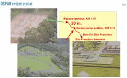
Oleoduto Santa Catarina-Parana (OSPAR) pipeline (Fig. 3) consists of about 117 km of 30-in. line from Sao Francisco do Sul Terminal and pump Station to Paraná terminal. It has one intermediate pump station at Itarare, at about KM 57.5. The mainline has eight sectionalizing valves (V1 to V8), excluding the pump stations and terminal-valving facilities.
The pipeline has a number of small river crossings, but it has one major crossing at Baia do Sao Francisco of about 2.5-3.0 km. OSPAR carries crude oil to REPAR refinery and has been operational since 1975.
The leak-rupture assessment principle is based on code requirements for determining remote valve operation. To optimize and determine which of the pipeline valves must be automated for remote operation, however, the simulation compared spill volumes at selected rupture locations for the two cases of either automating all existing valves or only automating selected mainline block valves for remote operation.
The simulations did not consider a third scenario, i.e., the case in which none of the mainline block valves was automated. The pipeline segmental volumes for the leak locations considered were calculated to be much larger than the maximum leak volume, according to criteria adopted by Transpetro, and therefore did not justify the third scenario.
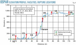
Fig. 4 shows the OSPAR pipeline elevations profile, location of existing valves, and location where ruptures were considered for simulation. With the simulation it was possible to review the amount of spill likely to occur in the event of a rupture.
This analysis indicated that spill volumes would be much greater in some locations as compared to the maximum spill criteria (e.g., 6,500 cu m at KM 48.5 rupture location vs. the maximum spill criteria of 3,170 cu m). Hence, check valves were incorporated at strategic locations to reduce any spill volume below the maximum specified by the criteria.
The simulation and subsequent site visit provided several conclusions:
Although current valve spacing meets code requirements, a significant spill cannot be avoided without valve automation and installation of check valves at strategic locations along the ROW.
Valves V2, V3, V5, and V6 require automation.
Check valves also need to be installed at KM 40, 48.5, 54, 61, and 73.5 to reduce spills to below the maximum specified criteria and to mitigate the environmental effects at HCA locations. HCAs included Rio Braco (now called Sao Joao), which drains into Baia Sao Francisco, and Barragem Vossoroca (dam), which provides water for power generation. Both are environmentally sensitive areas.
A transient simulation study was also performed to ensure that a valve-closure timing of 3 min as well as rapid shut down of the Itarare pump station would not damage pipeline operation by reaching the maximum operating pressure of the pipeline.
Simulation included closing each valve and tracking upstream dynamic pressures. In this case, it was assumed that applicable upstream pumps were operational if such a valve closure occurs.
The results of a simulation comparing maximum pressures created by valve closures to the maximum allowable operating pressure (MAOP) of the pipeline indicated that the MAOP of the pipeline would not be exceeded as a consequence of rapid valve closures.
The effect of a rapid shutdown of the Itarare pump station was also examined, both with and without the proposed check valves. Results indicated that rapid shutdown of the station would not adversely affect the MAOP of the pipeline.
*ORBEL II pipeline
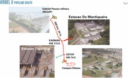
Oleoduto Rio-Belo Horizonte (ORBEL II) pipeline (Fig. 5) consists of about 358 km of 24 in. from Campos Eliseos to the Gabriel Passos refinery (REGAP) at Betim, state of Minas Gerais, near Belo Horizonte. It has two intermediate pump stations: Estaçao De Tapinhoa at about KM 74.5 and Estaçao da Mantiqueira at KM 173.6. This mainline has 29 sectionalizing valves, including the pump stations and terminal suction and discharge valving facilities. ORBEL II has been operational since about 1982.
No check valves are installed along this pipeline. The pipeline has about 42 river, stream, and canal crossings, but it has only 1 major river crossing, at Rio Paraiba at about KM 69.5-70. At this crossing there are three small mid-river islands.
The pipeline was reviewed for mainline valve automation because its ROW traverses a rapid elevation gain (KM 25-28) in an urbanized area and crosses many rivers and environmentally and geotechnically sensitive areas.4 There are several large communities near the ROW as the pipeline approaches Belo Horizonte. Also, the pipeline ROW parallels Rio Paraopeba (at about KM 280) along a river bend. In a rupture, the community and the adjacent sensitive areas could be affected. The same procedure as applied to OSPAR pipeline was followed for determining valve automation and possible additional valving arrangement to ensure that pipeline and the environment are protected in the event of a rupture or leak.
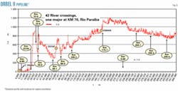
Valve automation analysis was thus based on a leak-rupture simulation (to minimize spill) and a site investigation to ascertain HCA. Fig. 6 shows the Orbel II pipeline elevation profile and the locations for which ruptures were simulated.
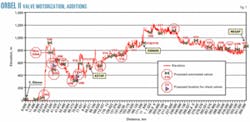
The assessment indicated that while valve spacing along the ORBEL II mainline meets code requirements, significant spills cannot be avoided without selected valve automation and installation of additional block and check valves at strategic locations along the pipeline. Fig. 7 summarizes the proposed valve motorization and additional valving arrangements.
During site reconnaissance for HCA determination, all proposed new valve locations were also confirmed for suitability and access. An example is the proposed location for Check Valve CV No. 2 (at about KM 37.82).
As with OSPAR, the study also included dynamic simulations of the pipeline subjected to sudden valve closure. Evaluation was thus made of ORBEL II valve closures to ensure that the pipeline would not see high-pressure surges and also to decide the appropriate valve closure timing.
Simulation included closing each valve and tracking upstream dynamic pressures. In this case, it was assumed that applicable upstream pumps would be operational if such a valve closure occurs.
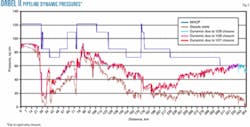
Fig. 8 shows the effect of rapid closure of valves V27, V28, and V29. As can been seen, dynamic pressures caused by closures of block valves V28 and V29 exceed MAOP of the pipeline but only marginally (62 kg/sq cm dynamic pressure vs. 60.5 kg/sq cm allowed). Such a small margin falls well within the 10% surge pressure allowed by ASME ANSI B31.4.7
The criteria adopted by Transpetro for this study consider that in a rupture, upstream pump stations are always shut down before closure of the relevant downstream block valves adjacent to a rupture location. In this situation and as can be seen from the comparisons in Fig. 8, no dynamic over pressurization will result if this procedure is followed.
Acknowledgments
The authors thank the management of Petrobras Transporte SA (Transpetro) and Enbridge Technology Inc. for their support throughout this study and the permission for the publication of this article.
References
1. Trench, C., and Sturbitts, C., "Oil Pipeline Safety" April Research Update, Association of Oil Pipelines, April 2000, www.aopl.org.
2. Etkins, D.S., "Analysis of Oil spill trends in the US and worldwide" Proc. Int. Oil Spill Conf., Tampa Fla., Mar. 26-29, 2000, pp. 1291-1300.
3. US Department of Transportation, Office of Pipeline Safety, "Liquid accident Yearly Summaries (1986-2002)," http://ops.dot.gov/stats/tran_sum.htm 10. API Standard 1130 2002, "Computational Pipeline Monitoring for Liquid Pipelines."
4. Mohitpour, M., Trefanenko, Bill, Tolmasquim, S.T., and Kossatz, H., "Oil Pipeline valve Automation for Spill Reduction," presented at Rio Pipeline Conference, Hotel Continental, Oct. 21-24, 2003.
5. Lentz, S.A., Felleman, F., "Oil Spill Prevention: a Proactive Approach," proc. Int. Oil Spill Conference, Apr. 6-10, 2003.
6. Mohitpour, M., Gloshan, H., and Murray, A., "Pipeline Design and Construction—A Practical Approach," ASME Press, New York, 2000.
7. ASME B31.4, " Pipeline Transportation Systems for Liquid Hydrocarbons and Other Liquids," New York: American Society of Mechanical Engineers, 1998.
8. US Department Of Transportation 49CFR, Section 195.
9. CSA, Z 662-03, "Oil and gas Pipeline Systems," Canadian Standard Association, Etobicoke, Ont.
10. API Standard 1130 2002, "Computational Pipeline Monitoring for Liquid Pipelines."
11. API Standard 1149 2001, "Pipeline Variable Uncertainties and Their effects of Leak Detectability."
12. API Standard 1160 2001, "Managing System Integrity for Hazardous Liquid Pipelines."
13. US Coast Guard 33CFR 155, Section 1050, "Code of Federal Regulation, Title 33, Vol. 2, Part 155, Section 1050, Response Development and Evaluation Criteria."
Based on a presentation to the 5th International Pipeline Conference (ASME), Oct. 4-8, 2004, Calgary.
The authors

Mo Mohitpour (tempsyspipe @shaw.ca) is president of Tempsys Pipeline Solutions Inc. and a principal consultant with Enbridge Technology Inc. involved in projects in Oman, Brazil, and Colombia. He has more than 27 years' experience in engineering, construction, and management of pipeline systems and associated facilities for oil, gas, condensate, batched products, specialty fluids transmission, storage, tankage, and distribution. Mohitpour is a registered professional engineer in several US states and Canadian provinces and is a member of ASME, the Institution of Mechanical Engineers (UK), and the Engineering Institute of Canada.

Bill Trefanenko has more than 24 years' experience in the oil and gas pipeline industry involving engineering design, construction, project management, operations, integrity and rehabilitation, maintenance, and management in both owner-operator and engineering consulting companies. He has managed projects in several countries, including Malaysia, Russia, Argentina, and Chile and has recently managed two planned maintenance contracts with Pemex Exploration & Production in the south and marine zones of Mexico. Trefanenko is currently manager of technology transfer for Enbridge Technology Inc.

Sueli Tiomno Tolmasquim ([email protected]) is pipeline technology coordinator for Petrobras Transporte SA (Transpetro), Rio de Janeiro. She has more than 15 years' experience with pipeline thermohydraulics analysis, design, leak detection, and new technologies evaluation.
Tolmasquim holds a BS in mechanical engineering from the Federal University of Rio de Janeiro and an MS in mechanical engineering from the Catholic University in Rio de Janeiro.

Helmut Kossatz (helmut.k@ stanfordalumni.org) joined Petrobrás in 1970 and has worked in the transportation department in planning and design of new pipeline systems. At the company's corporate university, he teaches courses for the company's new engineers, as well as advanced courses for engineers and geologists in a variety of subjects such as pipeline planning and design, pipeline hydraulics, engineering economy, finite element analysis, and several branches of mathematics.Kossatz also has worked in the company's research center where he developed a real time transient model for pipeline leak detection. Currently Kossatz works for Transpetro, where he is a senior engineer and technical consultant. Kossatz holds a BSc in mechanical engineering from the Federal Univesity of the State of Rio de Janeiro, and an MS in mechanical engineering from Stanford University.