Kentucky refiner reconfigures resid FCC unit for normal FCC service
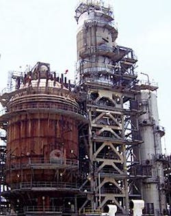
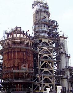
In 2004, Marathon Ashland Petroleum LLC revamped a 20-year-old, 40,000 b/sd resid FCC (RFCC) unit into a 95,000-b/sd FCC unit (Fig. 1) in its Cattlesburg, Ky., refinery. The revamped FCC unit now processes entirely hydrotreated feedstock to produce low-sulfur gasoline.
The revamp has also resulted in less SOx and NOx emissions from the regenerator flue gas. This transformation represents a unique approach to using existing assets, which includes the revamp of an existing feed hydrotreater and decommissioning of a 1950s vintage FCC unit.
The reconfigured RFCC unit restarted in February 2004 and has met all of Marathon Ashland’s expectations.
The company’s goal was to produce gasoline with an average sulfur content of less than 30 ppm. Blending FCC gasoline containing up to 45-ppm sulfur with ultralow-sulfur gasoline from other process units would achieve this goal.
Its target for flue gas SOx emissions was 25 ppm on a 365-day rolling average. Its target for flue gas NOx emissions was not specific, but the refiner expected a substantial reduction. The project’s success was largely due to the flexibility of the regenerator.
Fluid catalytic cracking
FCC units convert the heavy portion of crude oil into usable products such as LPG and gasoline. Gasoline produced in FCC units account for about half of the typical refinery gasoline pool, while other processes such as reforming, isomerization, and alkylation provide the remainder.
Sulfur tends to concentrate in the heavy portion of crude and ultimately shows up in the FCC products, primarily gasoline and cycle oils. FCC gasoline therefore contributes a disproportionate amount of sulfur to the gasoline pool.
Sulfur is also in coke, a by-product of the cracking process. The coke is subsequently burned in the FCC unit regenerator, which releases sufficient heat to power the entire process. Sulfur in the coke is oxidized to sulfur oxides during combustion and is subsequently released along with the flue gas.
The market demand for low-sulfur gasoline has increased worldwide in recent years because regulations have reduced the maximum allowable sulfur content in gasoline. Likewise, public regulators have also reduced the maximum allowable SOx emissions from stationary sources, including FCC units.
Refinery history
The Catlettsburg refinery was the refinery originally owned by Ashland Oil Co. and has been in continuous operation since 1917. In 1956, a new FCC unit was commissioned for the conversion of vacuum gas oil.
In 1983, an RFCC unit was commissioned, which included multiple first-of-kind technologies. Two low-pressure feed hydrotreating units were later commissioned.
By 2003, the refinery had a crude capacity of 240,000 b/sd, with a typical FCC charge rate of 55,000 b/sd and a typical RFCC charge rate of 40,000 b/sd.
UOP and Ashland Oil Co. jointly designed the RFCC unit, which was designed to process an unhydrotreated mixture of reduced crude (atmospheric tower bottoms), sour vacuum gas oil, deasphalted oil, and vacuum tower bottoms.
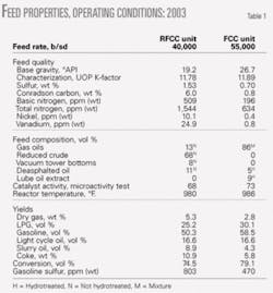
Table 1 shows typical feed properties and operating conditions for the RFCC unit and FCC unit in 2003.
First-of-kind technologies
When commissioned in 1983, the RFCC unit included multiple first-of-kind technologies:
• Unique two-stage regenerator in a single vessel.
• Flow-through shell and tube catalyst cooler.
• Vented riser reactor with single-stage cyclones.
• Elevated radial feed distributors.
• Lift gas in the lower riser for nickel passivation.
• A back-mixed shell and tube catalyst cooler added in 1988.
Since 1983, UOP has commissioned seven RFCC units with two-stage regenerators.
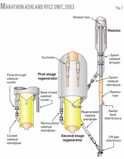
Fig. 2 shows the configuration of the Catlettsburg RFCC unit in 2003, its last full year of operation.
The Catlettsburg RFCC regenerator contains two stages in a single vessel. About 75% of the air is consumed in the first stage, which operates in partial combustion. The remaining air is consumed in the second stage, which operates in complete combustion.
Flue gas from the second stage flows to the first stage through vent tubes in a ring around the first-stage air distributor. The combined flue gas exits through cyclones at the first-stage regenerator’s top. The combined flue gas is oxygen deficient, resulting in overall partial combustion.
Spent catalyst from the reactor initially flows to the first-stage regenerator where it is partially regenerated. Some of the catalyst is then cooled in the flow-through catalyst cooler and transferred to the second stage via the cooled catalyst standpipe. The circulating catalyst standpipe transfers the remaining catalyst to the second stage.
The backmix catalyst cooler provides supplemental cooling. The catalyst is then fully regenerated in the second-stage regenerator and returns to the reactor riser via the regenerated catalyst standpipe.
Regenerator temperatures can be quite high when processing feeds containing high concentrations of Conradson carbon (concarbon), which results in a low catalyst-to-oil ratio and poor conversion.
To maximize the catalyst-to-oil ratio, the two-stage regenerator was designed to operate in partial combustion overall, resulting in a higher catalyst-to-oil ratio than a comparable operation in complete combustion. The catalyst coolers provide external cooling of the catalyst to improve the catalyst-to-oil ratio further.
Catalyst deactivation increases with higher water partial pressure and temperature (hydrothermal deactivation). With high concarbon feedstocks, hydrothermal deactivation can result in a substantial increase in fresh catalyst cost required to maintain activity.
Because hydrogen oxidizes readily in the combustion process, most of the hydrogen is converted to water in the first stage and leaves directly with the flue gas. Most of the water is thereby removed, and the catalyst cooled before reaching the second stage.
In the second stage, the catalyst fully regenerates at a relatively low temperature and low water partial pressure, but with excess oxygen.
Another factor that contributes to catalyst deactivation is vanadium in the feed, which accumulates on the catalyst and can poison the catalyst’s zeolite crystals.
Vanadium is most harmful in the fully oxidized state (V2O5) and in the presence of water at high temperatures. Any vanadium attached to the catalyst, however, does not fully oxidize until it reaches the second stage where it is less harmful due to the lower temperature and lower water partial pressure. This design philosophy allows for greater catalyst activity retention at high metals loadings.1
Nickel in the feed will also accumulate on the catalyst where it can act as a strong dehydrogenation agent. Unchecked, the accumulated nickel will lead to high hydrogen yields.
Recycled dry gas from the gas concentration unit effectively passivates the catalyst’s active nickel sites, thus reducing the hydrogen yield. The Catlettsburg reactor included elevated radial feed distributors with a long lift section that used recycled dry gas as the lift medium to passivate the nickel sites before feed injection.
The reactor also included a single-stage vented riser, which was state-of-the-art in 1983. This riser termination device relied on the momentum of the catalyst leaving the riser’s top for the initial stage of separation, followed by a single stage of conventional cyclone separators.
Because the regenerator operated in partial combustion, a CO boiler was required to incinerate CO in the flue gas and recover the released heat. The original design feedstock for the RFCC unit had a high sulfur content; Marathon Ashland therefore anticipated high SOx emissions from the regenerator flue gas.
The original installation included a fluidized limestone (calcium carbonate) boiler to lower the SOx emissions. This unique equipment captured the SOx and served as a CO boiler. Bag houses were provided for final cleanup of limestone dust and catalyst fines.
The challenge
In 1999, Marathon Ashland embarked on an asset development plan for the Catlettsburg refinery. The company primarily wanted to produce low-sulfur gasoline and reduce refinery emissions. Another major goal was to decommission the 1950s-era FCC unit due to reliability concerns and maintenance costs.
Two general schemes were available to meet these goals: pretreating the FCC feed or post-treating the FCC gasoline. Both schemes are commercially proven in the production of low-sulfur gasoline; however, only the feed pretreating option could reduce the concarbon concentration in the feed. A lower-concarbon feed would allow Marathon Ashland to increase the RFCC unit’s capacity to 95,000 b/sd, which would allow the refiner to shut down the old FCC unit.
The feed pretreating option had several other advantages and synergies. The company could:
• Revamp an existing FCC feed hydrotreater for higher throughput and severity.
• Significantly reduce SOx and NOx emissions, which would meet the expectations of a consent decree with the US Environmental Protection Agency.
• Operate the RFCC unit in complete combustion with a clean hydrotreated feed. SOx-reducing additives are more effective in complete combustion vs. partial combustion operations. SOx-reducing additives would then be sufficient for reducing the SOx emissions to below the desired limit.
• Avoid capital and maintenance costs associated with the old FCC and limestone boiler.
• Improve product value with a hydrotreated feed, although at a substantial investment and operating cost.
• Reduce sulfur content in the light cycle oil, which would reduce the cost of producing low-sulfur diesel in the future.
In addition to the RFCC revamp, Marathon Ashland revamped the existing low severity, 40,000-b/sd FCC feed hydrotreater to produce 60,000 b/sd of FCC feed with a sulfur level of 750 ppm. Another existing hydrotreater was reloaded with fresh catalyst and slightly modified to produce 35,000 b/sd of FCC feed with 500-ppm sulfur. The combined 95,000 b/sd of hydrotreated FCC feed had a sulfur concentration of 660 ppm.
The company’s preliminary studies indicated that this level of feed sulfur would be sufficient to produce an FCC gasoline with a sulfur level of about 45 ppm. The old FCC unit could be decommissioned and the RFCC unit could be modified to process all 95,000 b/sd of hydrotreated FCC feed.
Improved product selectivity due to feed hydrotreating would improve the return on investment.
Due to the large capital investment for this project, Marathon Ashland conducted extensive pilot-plant tests at its research and development facility in Catlettsburg. Hydrotreater feed samples from the refinery were tested in a hydrotreater pilot plant. Products from the hydrotreater pilot plant were then tested in a circulating-riser FCC pilot plant.
The FCC pilot-plant tests used equilibrium catalyst from a commercial FCC unit. The pilot-plant tests confirmed the licensor yield estimates for the FCC feed hydrotreating unit and the RFCC unit.
Haldor Topsøe AS was the technology provider for the hydrotreater revamp, which was commissioned in June 2003.2 The RFCC unit revamp was commissioned in February 2004.
RFCC unit modifications
A UOP preliminary analysis confirmed that the reactor and regenerator shells for the RFCC unit could be retained when processing 95,000 b/sd of clean hydrotreated feed. The regenerator, reactor, and other systems were modified.
Regenerator modifications
In the new configuration, the coke yield as a percentage of the feed would be substantially lower due to the low concarbon feedstock. This would normally result in a lower flue gas rate, which would debottleneck the regenerator cyclones. Due to increased capacity, however, the flue gas rate would actually increase. If left unchecked, this would result in high cyclone velocities and increased erosion.
To accommodate the increased flow rate, Marathon Ashland increased the regenerator operating pressure; this kept the cyclone velocities at a sustainable rate.
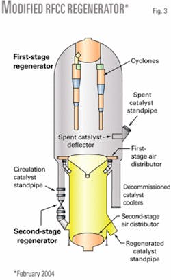
Due to the low concarbon feedstock, catalyst coolers were not needed to maintain the catalyst’s activity. The tube bundles were removed from both catalyst coolers and the shells were left in place.
The existing circulating catalyst standpipe was not large enough to accommodate the increased catalyst circulation rate. The company therefore converted the cooled catalyst standpipe from the flow-through catalyst cooler to a secondary circulating catalyst standpipe. A unique air distributor was installed to ensure proper fluidization at the entrance to this standpipe.
Fig. 3 shows the modified regenerator.
Coke combustion kinetics in the regenerator are a strong function of the operating conditions and rise exponentially with temperature. A low regenerator temperature can limit the oxidation of CO to CO2, resulting in high afterburn and high CO emissions.
The carbon on regenerated catalyst can also be quite high with a low regenerator temperature; this blocks active catalytic sites and reduces the effective activity of catalyst returning to the reactor. This is particularly true for units operating in oxygen-deficient partial combustion.
Because the anticipated feed would be severely hydrotreated, the expected regenerator temperature would be much lower than with resid feed. Technology that maximizes catalytic cracking while suppressing thermal cracking was implemented in the reactor. This advanced technology would reduce the regenerator temperature further.
The regenerator temperature would increase somewhat with a higher feed temperature, which was set at the maximum temperature attainable using circulating slurry for heat exchange. Even at the maximum attainable feed temperature the coke-burning kinetics could be compromised. UOP therefore recommended operating both stages in complete combustion.
This resulted in a higher dense-bed temperature than a comparable operation in partial combustion. The net result was less carbon on regenerated catalyst and a higher effective catalyst activity and conversion potential compared to partial combustion.
Due to the large (45 ft) vessel diameter and lower regenerator temperature, catalyst distribution across the first stage was more critical. Good catalyst distribution requires even mixing of the coke attached to the catalyst with the air rising in the bubbling bed.
Poor distribution can lead to localized afterburn, particularly in complete-combustion regenerators. UOP therefore recommended an advanced spent-catalyst deflector design for the first-stage regenerator. This equipment delivers the catalyst deeper into the regenerator than the previous design and distributes it over a wider area. Use and placement of the catalyst recirculation standpipes also promoted effective mixing.
Good afterburn control relies on good oxygen distribution across the bubbling bed. Marathon Ashland, however, was concerned that oxygen distribution in the first-stage regenerator would be uneven due to the vent tubes that transfer oxygen-rich flue gas from the second stage to the first stage.
This has not historically been a problem for two-stage regenerators, all of which operate in partial combustion; however, no refiner had ever operated a two-stage regenerator in complete combustion.
To address this concern, UOP conducted a detailed hydraulic analysis of the first-stage regenerator. The results indicated the oxygen maldistribution would be minimal and any afterburn could be controlled with CO promoter.
The crushed limestone boiler relied on a complicated solids-handling system to move large quantities of fresh and spent limestone. This system required substantial maintenance resources. Procurement of fresh limestone and disposal of spent limestone was also expensive.
The revamped unit should produce much less SOx emissions due to the improved feed hydrotreating and SOx-reducing additives. Marathon Ashland therefore planned to stop using limestone to control SOx emissions; however, the refiner wanted to continue firing supplemental fuel in the boiler to produce steam. To minimize thermal NOx formation in the boilers, the existing burners were replaced with low-NOx burners.
Reactor modifications
Due to the increased feed rate, the velocity of catalyst exiting the vented riser should increase significantly. The higher velocity would likely result in more equipment erosion and catalyst attrition.
To quantify the extent of increased catalyst attrition, UOP and Marathon Ashland conducted extensive cold-flow model tests at the Particulate Solids Research Institute, Chicago. The main concern was that greater catalyst attrition would increase the failure rate of pumps and related equipment in the circulating slurry system, as well as increase the cost of catalyst disposal from slurry product tanks.
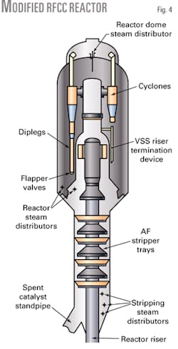
Based on the testing results, the company deemed the increased catalyst attrition rate as unacceptable. The existing vented riser was removed and replaced with UOP’s VSS riser-termination device. A new, larger-diameter riser was installed for residence-time optimization.
The existing cyclones were reused and two new cyclones were installed in open slots, which were reserved for future capacity increases. The reactor operating pressure also increased to maintain the cyclone inlet velocity at a sustainable rate.
Fig. 4 shows the revamped reactor.
In the original design, dry gas from the tail end of the gas concentration unit was recycled to the riser and used as lift gas for dehydrogenation control. Due to the clean, low-nickel feed, lift gas was no longer needed and could be eliminated. This reduced the effective dry gas flow rate and helped debottleneck the gas concentration unit.
New feed distributors were required to accommodate the increased capacity. To minimize sour-water disposal costs, Marathon Ashland installed UOP’s low-steam Optimix LS feed distributors.
The company also requested advanced stripper technology to maximize the catalyst circulation rate and improve conversion. The reactor modifications also included installation of UOP’s AF stripper trays.
Other modifications to the catalyst section included a new regenerated catalyst slide valve to accommodate the greater catalyst-circulation rate and modifications to the flue-gas slide valve to accommodate the higher anticipated pressure drop.
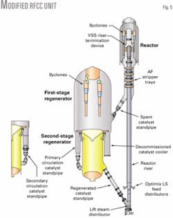
Fig. 5 shows a diagram of the combined catalyst section.
Other modifications
Because the revamp was so extensive, substantial modifications were also required for downstream and auxiliary equipment. The other major modifications included:
• A new main air blower.
• A new wet gas compressor.
• Modified circulating slurry system and feed preheat system.
• New main fractionator trays.
• Modifications to the gas concentration unit, gasoline treating unit, LPG treating unit, and C3-C4 splitter unit.
• Modifications to the relief system and offsite utilities.
Revamp performance
The revamped RFCC unit was commissioned in February 2004. UOP provided technical advisor support for equipment checkout, procedure review, and start-up assistance. The unit has been in continuous operation since commissioning. The revamped unit’s performance has exceeded Marathon Ashland’s expectations.
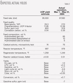
Table 2 shows a summary of the postrevamp yields and the UOP yield estimate that was used for project justification.
Regenerator performance
The regenerator’s performance since the revamp has also exceeded expectations. The extent of afterburn is typical for a low temperature, bubbling-bed regenerator. Afterburn is easily controlled with a typical regimen of nonplatinum-based CO promoters.
Temperature distribution at multiple levels is also uniform, which indicates good catalyst and oxygen distribution. Carbon on regenerated catalyst is typically less than 0.05 wt %.
Initial operation of the revamped unit relied on a platinum-based CO promoter for afterburn control. It is well known, however, that NOx emissions increase with greater use of platinum-based CO promoters. Subsequently, Marathon Ashland started using a nonplatinum-based CO promoter, and a NOx-reducing additive, which reduced the NOx emissions to about 35 ppm at the stack.
The new low-NOx burners in the CO boiler still contribute somewhat to the total NOx measured at the stack, so the NOx level leaving the regenerator is actually less than 35 ppm.
The SOx-emission permit for the revamped RFCC unit is 25 ppm on a 365-day rolling average basis and 50 ppm on a 7-day rolling average basis. The revamped unit has easily met these requirements using SOx-reducing additives. Switching the RFCC unit to complete combustion was the main factor that enabled the company to discontinue use of limestone in the CO boiler in favor of SOx-reducing additives.
Another benefit of the staged regeneration is less fresh catalyst consumption. Because the first-stage regenerator still removes most of the carbon and water, hydrothermal deactivation is minimal. Typical fresh catalyst additions have been 0.03-0.06 lb/bbl.
Table 3 shows a summary of flue gas emissions at the stack for the old FCC unit and RFCC unit before the revamp vs. the RFCC unit after the revamp. ✦
Acknowledgments
The authors thank Jeff Sexton and Mike Skurka of Marathon Ashland LLC Petroleum for providing the operating data presented in this article.
References
1. Turner, J., “Advanced Resid FCC Technology Demonstrated in MAP LLC’s Catlettsburg RCC Unit,” presented to the NPRA 2004 Annual Meeting, NPRA paper AM-04-16, Mar. 21-23, 2004, San Antonio.
2. Patel, R., “FCC Hydrotreater Revamp for Low Sulfur Gasoline,” presented to the NPRA 2004 Annual Meeting, NPRA paper AM-04-33, Mar. 21-23, 2004, San Antonio.
3. Upson, L., Daline, I., and Wichers, W.R., “Heat Balance the Key to Cat Cracking,” presented to the Third Katalistiks Fluid Cat Cracking Symposium, May 26-27, 1982, Amsterdam.
The authors
Patrick Walker ([email protected]) is an FCC process specialist in UOP LLC’s refining technical services group, Des Plaines, Ill. His duties include commissioning new and revamped FCC units, troubleshooting, optimization, performance benchmarking, process development, and training. Prior to his current assignment, Walker worked in UOP’s engineering department where he conducted basic engineering and process studies specializing in FCC reactors, regenerators, main fractionators and gas concentration units. He holds a BS in chemical engineering from th euniversity of Illinois.
Paolo Palmas ([email protected]) is the engineering FCC process specialist for UOP LLC, Des Plaines, Ill. He has been with UOP since 1977 and has held a variety of positions in research and development, technical services, and engineering. His responsibilities include managing UOP’s FCC technology for the engineering group, which includes providing design expertise and technical support for project work, managing design procedures and tools, supporting sales activities, and developing technical solutions and innovations for new projects. Palmas holds a BS in chemical engineering from Drexel University, Philadelphia.
Based on a presentation to the National Petrochemical & Refiners Association Annual Meeting, Mar. 13-16, 2005, San Francisco.
