Saudi experience: Leak-detection systems need careful evaluation
Experience dealing with leak-detection system technologies from design to maintenance indicates that there is no single dominant leak-detection technology.
A single leak-detection technology for the great diversity of service conditions, pipeline installations, fluids, and topologies of real pipeline applications remains a distant objective. Each technology has strengths that can make it a cost-effective solution for a specific application.
There is a wide range of LDS products, from relatively simple “sniffing” sensors to elaborate, real time, pipeline-modeling software. During design of an LDS for a particular pipeline application, more than one may meet the performance requirements; however, installation and maintenance costs can vary significantly.
What is the cost-effective solution? The differences in costs come from the abilities of each system in key performance areas. These differences must be addressed at early design stages of pipeline projects to arrive at the cost-effective solution for a specific application.
The performance of an LDS depends strongly on operating conditions, including available infrastructure at field, communications, and monitoring levels. In the end, the operational performance of an LDS is a combination of the total contribution of individual components of both the system and the infrastructure.
In real-life conditions, some LDS, although powerful and sophisticated, cannot meet acceptable performance levels. Why? The author’s experience in design, installation, and maintenance of LDS technologies-over a pipeline network transporting a variety of fluids-indicates that these systems have inherent technical limitations that affect their ability to reach the required performance levels cost effectively.
Hence, selecting cost-effective solutions requires an examination of performance and costs in real-life operating conditions. This article looks at a practical approach to these problems from the end-user perspective.
Pipeline leaks, detection
Frequency and magnitude of leak incidents vary among pipeline operators and even between two segments of the same pipeline. Many companies have never experienced a rupture in years of operation. Others exert significant effort to ensure the integrity of their facilities with little success.
Recent investigations (ASME publication B31.8S-2001 2.2 “Integrity Threat Classification”) revealed that the causes of pipeline leaks have origins in “22 worldwide common threats” to the integrity of pipelines. These are found in five categories:
• Corrosion (internal and external).
• First and second-party damage; (company and partners working for the company).
• Third-party damage (outsider’s damages, construction activity, sabotage).
• Materials failures (valve leaks, weld and pipe seam leaks).
• Natural forces (floods, earthquakes).
The degree of exposure of pipelines to these threats determines how leak incidents take place in every pipeline. Pipelines in highly populated areas with intense construction activity may experience high rates of third-party-related leaks.
In other areas, corrosion and natural forces may be the predominant threats. To deal with leaks, pipeline operators have developed strategies oriented to prevent leaks and mitigate their consequences.
Pipeline operators utilize several protection techniques, such as cathodic protection for external corrosion, corrosion inhibitors for internal corrosion, and fencing and barricades for third-party damages. Worldwide statistics of pipeline failures show that prevention techniques can reduce significantly both frequency and magnitude of leak incidents.
But pipelines still have leaks, despite the effectiveness of these techniques, and in the event of a leak, the pipeline operator must be able to respond effectively and in a timely manner. That means good leak-detection tools must be in place. Accurate early detection is important. Although having an LDS in place does not prevent leaks, it helps to mitigate their consequences.
Leak consequences
An effective leak-detection tool is important to pipeline operators because pipeline leaks translate directly into tangible and quantifiable losses. Clean-up costs, product losses, and service-interruption costs, are just some examples.
In addition, leaks may lead to human injury or death and severe damage to the environment. Pipeline operators are responsible for the integrity of their facilities and damages to third parties for negligence or deficiencies in ensuring the integrity of pipeline facilities may result in significant losses.
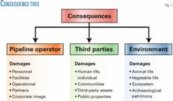
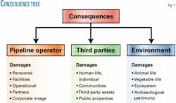
Pipeline leaks have consequences in three main areas: the pipeline operator, involving personnel, partners, and facilities; third parties, i.e., people, their assets, and public properties; and the environment. Fig. 1 shows the consequence of leak-incidents and potential damages.
In leaks, the magnitude of the damages directly relates to the volume of fluid released. LDS technologies allow end-users to detect faster and locate more accurately pipeline leaks, which reduces response time. But improving leak-detection time does not necessarily imply better response time. Consequences depend on other factors, such as response time and the travel time to the incident site. Hence, fast and more-accurate leak detection is necessary but not in itself sufficient to reduce the consequences of pipeline leaks.
The consequences to people and the environment are usually expressed as risk values (for people it is individual risk-fatalities/year). For example, several factors must be considered to determine how much an LDS can contribute to reducing the level of risk to people living in a given area.
To quantify a possible contribution of LDS in relation to risk, the risk-assessment tools (i.e., simulation software) should be able to determine risk values in different “what-if” scenarios, such as estimating risk with and without LDS in place. The results of this exercise will be strongly affected by assumptions made to the proposed scenarios and may lead to unrealistic conclusions.
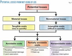
When the LDS detects a leak within the specified detection time, it contributes to a certain degree in reducing the potential losses (Fig. 2). Losses can be classified as material or nonmaterial. Material losses relate to tangible substances and services easy to quantify, and nonmaterial for intangibles and items difficult to quantify. Damages to third-party assets are tangible, while damages to corporate image are intangible.
LDS has a minimum-achievable detection time, and a certain amount of fluid is inevitably released to the environment during this time. The volume of fluid released from the exact time when the leak takes place until the leak is effectively detected is part of the unavoidable losses for the LDS. Similarly, losses derived from service interruption are part of the unavoidable losses.
In the event of a leak, in particular medium-to-full bore rupture leaks, the service is interrupted by shutting down mainline valves and stopping any pumps. Losses from this interruption cannot be avoided even when an LDS is used.
LDS, old methods
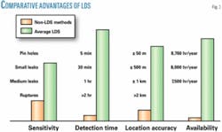
In the past, the methods used to detect pipeline leaks, such as direct visual inspection, remote pipeline monitoring (e.g., human-observer at remote supervisory control and data acquisition centers) and “sniffing” sensors (e.g., combustible, toxic gas sensors) were ineffective for detecting and locating leaks in real-life pipeline conditions (Fig. 3).
The sensitivity of gas sensors varies widely according to both the pipeline installation and ambient conditions. Gas sensors cannot locate leaks unless the leak develops relatively close to it. In practice, a large number of sensors would be needed to achieve acceptable sensitivity and accuracy levels over a relatively short pipeline length (1 mile). Even more advanced solutions, such as open-path infrared sensors, require tens of units per mile of pipeline, and that is impractical.
Visual detection methods also have strong performance limitations. To determine whether there is an actual pipeline leak, the observer at the SCADA center must verify the upstream and downstream pressure values, setting of control systems, functioning of instruments, status of main line valves, and mechanical equipment. This verification process may take from several minutes to several hours.
In addition to poor sensitivity and accuracy, visual methods are not reliable. Consider a small leak in a gas pipeline upstream of a pressure control station equipped with standard control valves. At the point of the leak, the pipeline pressure drops proportionally to the leak flow. As a result, the control valves open to sustain the pressure, increasing the leak flow even more. The pressure starts to fluctuate until equilibrium is reached with the valves 100% open. These fluctuations may last for hours.
This suspicious “leak scenario” may look quite similar to normal conditions, and daily changes of ambient temperature may produce similar pressure effects. After time-consuming verifications, the SCADA center operator may finally declare a “true leak.”
Neither visual methods nor sniffing sensors are reliable. Wind speed and direction, presence of dust in the air, and soil type for underground pipelines are factors that may decide if a gas sensor can detect a leak.
Both on-site and remote visual detection are noncontinuous methods. The observer may not be present when the leak takes place. Pipeline leaks are random and unpredictable events. Monitoring of leaks must be a continuous and full-time task. None of the visual detection methods can provide continuous monitoring. This deficiency reduces dramatically the chances of detecting pipeline leaks.
Advantages of LDS
To decide which pipeline requires LDS means considering risk, operations, and economics. The selection of candidate pipelines is based on the results of a consequence assessment. This assessment quantifies the severity of the operational, economical, and risk impact of potential leak incidents. An LDS will help mitigate the effects in these three areas.
The severity of the effect has common factors. For the risk effect, we focus on pipelines identified during risk-based assessments. The operational effect focuses on pipelines in critical services. The economical effect covers pipelines that can develop leaks with a high-loss potential.
Selecting LDS solutions
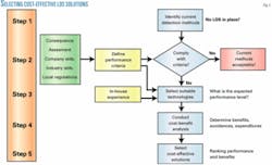
There are five steps in the proposed selection process (Fig. 4):
1. Identify the current leak-detection methods of the target pipelines.
2. Assess the performance of the existing leak-detection methods according to predefined performance criteria to determine if the target pipeline requires a new LDS.
3. Estimate the expected performance level of the available LDS technologies taken from the vendor list to determine compliance with performance criteria.
4. Look at the benefits of using the selected systems by estimating cost avoidance and expenditures for installation, operation, and maintenance.
5. Select the most cost-effective solutions by ranking the preselected LDS candidates according to their performance levels and expected benefits.
The first stage examines current leak-detection methods and identifies their performance strengths and weaknesses under operational conditions. In this stage, the key questions are: What kind of detection methods are in place and how do they perform?
There are several techniques involved. One simple and easy technique is a quality-performance appraisal of the methods by scoring relevant performance areas according to five non-numeric grades of quality: bad, poor, acceptable, good, and excellent. This scoring must define these five “quality grades” in every performance area.
Relevant information collected includes:
• Past leak-incident records.
• Response-plan procedures.
• Design specifications of leak-detection methods or systems.
• Operational records (if LDS).
• Maintenance records (if LDS).
• Pipeline design and fluid data.
• Service conditions.
A questionnaire is distributed to emergency response and operations and maintenance personnel to complement the data-gathering process. This helps obtain sensible information about the current detection methods from several sources.
The performance areas must be consistent with the company’s definition and measures of performance in leak detection. Throughout the appraisal process, deficiencies in performance definitions and measures may arise, and this initial identification stage examines these problems.
An examination of the leak-detection practices should not be discarded at this stage. This includes an overview of:
• Company’s standards and procedures.
• Industry standards and practices.
• In-house lessons learned.
• Past performance-assessment results.
• Manufacturers’ recommendations.
• Other user experiences.
If current methods do not use any LDS technology and, especially, if performance definitions and measures are not yet well defined, a double check on the justifications that led to a new LDS may avoid unnecessary and costly installations.
A second round of verifications may conclude that current leak-detection methods are satisfactory and cost effective. If this is the case, installing a new LDS is not necessary.
LDS performance criteria
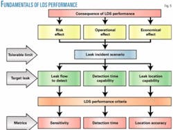
A widely used definition of performance for software-based LDS (API 1155) examines the concept of performance in four areas: sensitivity, accuracy, reliability, and robustness (Fig. 5).
In this classical approach, sensitivity addresses the detectability of leaks (often it also includes leak-detection time); accuracy refers to the system’s capability to locate leaks; reliability addresses the problem of false alarms; and robustness refers to stability under operational conditions.
This approach examines the basic functions of leak-detection systems that may apply to other LDS technologies, including gas-sensor solutions, sensitive cables, and acoustic-wave detection. Operability and maintainability also may be included. Depending on the technologies, the performance concept can be further extended towards other areas.
Besides the different approaches and definitions, the LDS performance assessment must reflect the system’s ability to detect the target leak event. Parameters, engineering units, and ranges of the performance measures must determine by a relatively simple examination whether the system is capable of detecting the target leak.
From the same perspective, the target leak event must be defined according to the results of the consequence assessment that quantifies the operational, economical, and risk effect of potential leak incidents. This assessment determines tolerable limits in these three areas and the characteristics of the leak incident scenario associated with tolerable limits.
The leak scenario is defined by characteristic factors, such as leak flow rate, leak-detection time, and leak location along the pipeline. Therefore, the target leak event must be expressed in terms of those factors.
Compliance
In this stage, the performance level of current leak-detection methods is quantified in order to determine compliance with the requirements of the application.
The methods in place will be assessed in every performance area according to the measures of the performance criteria. There are two possible scenarios for this assessment: either the existing methods do or do not use LDS technology.
In the first case, the assessment must quantify the basic functionality (sensitivity and accuracy) of the LDS. A numeric quantification determines if the existing LDS must be replaced by other, more-efficient technology. Other areas of performance, such as reliability and robustness, can be expressed in quality grades, although this will depend on the performance measures in those areas.
In addition, this performance assessment can be extended toward other areas, depending on the characteristics of the LDS. These other areas of performance may include:
• Flexibility. The ease of the system to be modified for the specific purpose of the application, including ability of interfacing with other systems (connectivity), the ease of reducing or expanding hardware architecture without increasing complexity (scalability), and the ability to integrate its architecture into a predefined infrastructure (adaptability).
• Complexity. The minimum requirements of hardware and software to meet the required performance level on a predefined pipeline topology.
• Susceptibility. The ability of the system to maintain the specified performance level under specific adverse conditions at field, communications, or display device levels.
Operation and maintenance areas may also be considered at this stage. These include:
• Operability under leak and nonleak conditions, including man-hours for start-up, configuration, testing, the need of special configuration tools, alarm features (e.g., sound, messages, and leak-location flags), the ability to override or execute commands to external devices, accessibility of users to configuration parameters, and security features.
• Maintainability, which evaluates the ease of being repaired, the cost-effectiveness of repairing or replacing the system, and the ability of the system to verify its status.
In the second case, if there is no LDS technology in place, it is likely that current methods will not meet the requirements in more than one area of basic functionality. Also in this case, the assessment must quantify performance of basic functions.
Practical experience conducting this selection process, however, demonstrates that the quality performance appraisal of the initial stage provides sufficient and valid information to determine if the existing leak-detection methods must be replaced.
Technology selection
At this stage, the operating conditions of the pipeline, such as the instrumentation hardware and software, communications and monitoring, type of fluid, flow regime, pipeline elevation profile, control systems, and mechanical equipment, already have been identified. In addition, any performance problems of former leak-detection methods, their causes and recommended corrective actions, are also available.
Based on these inputs, the LDS technology is determined that best meets the performance requirements of the pipeline or pipelines where the LDS is to be installed. The strategy is to estimate the expected performance levels of the available LDS technologies and to verify performance compliance. This process covers several phases, from a general overview of limitations to a thorough examination of specific areas of performance of the available technologies.
In Phase 1, the subject of analysis is the leak-detection principle utilized by each technology. Each LDS relies on a basic detection principle or mechanism that allows the system to perceive a leak or its by-products; they are either direct detection or inferred detection. For example, an LDS that uses sniffing sensors relies on a direct-detection principle. A mass-balance LDS relies on an inferred-detection principle.
For each LDS there are specific leaks that have no perceivable effects. These imperceptible leaks fall within the undetectable range of the system. Realizing these limitations helps discard unsuitable technologies.
A few basic questions are required:
• Are sniffing sensors able to detect underground pinhole spillages?
• Can the mass-balance approach detect small leaks in multiphase pipelines?
• Is the statistical pressure-flow detection technique suitable for leak detection during transients in batch-service applications?
• Does acoustic wave detection work in gas pipelines with high levels of background noise? Are there any “all-in-one” LDS products available?
Phase 2 focuses on practical limitations in design, installation, operation, and maintenance. The LDS is not an isolated entity; in the majority of operating pipelines the LDS shares infrastructure with other systems. From the simplest to the most sophisticated, the LDS technologies share a common hardware architecture of three levels: field devices, communication links, and monitoring devices.
Besides the hardware, more elaborate solutions include software packages with a variety of features. Within this context, every system can be placed into three categories: fully integrated, partially integrated, and standalone.
The suitable LDS solution must fit into the available infrastructure. For example, if a proposed LDS technology requires updated field instruments that the SCADA application cannot provide, it is probably not feasible to install such system.
In this phase, therefore, the goal is to identify those unavoidable limitations in infrastructure and technologies and to select the technologies that look more suitable for the application. This helps screen out factors that later may weaken performance of the selected LDS.
Phase 3 is the final engineering decision for the most technically suitable solution. This phase should estimate the expected performance levels of the LDS technologies that have passed the prior screening of Phases 1 and 2.
For this estimate (engineering forecast) there are different possible approaches, including:
• Off-line LDS software simulations.
• Monte Carlo simulations of leak algorithms.
• Engineering estimates (e.g., error propagation, confidence value estimate, stationary analysis, failure analysis).
• Industry recommended practices.
• Statistical estimates.
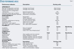
Table 1 shows various methods that can be used.
Quantifying performance
The leak-detectable threshold of the suitable LDS must be lower than the target leak. For volume and mass-balance LDS, the API 1149 method can provide a good approximation of the sensitivity level. However, this method treats systematic and random errors equally.
The total contribution of systematic errors produces in these systems a constant volume imbalance or “off-set” that by tuning and configuration can be reduced significantly. Nevertheless, random errors cannot be eliminated easily.
The detectable threshold has a theoretical limit of about 0.5% of the nominal flow rate for volume and mass-balance LDS technologies. That is an important limitation to this type of system because leaks of 0.5% of nominal flow are not tolerable in many operating pipelines.
For the statistical pressure and flow-detection techniques, one of the methods to determine if these techniques are appropriate is the stationarity analysis of the pipeline pressure and flow for the most representative operational scenarios. This analysis determines if the operating pressure and flow have strong or weak stationarity; in other words, whether or not there is a possible statistical mean-value that can be used as leak-detection threshold.
Since these methods are essentially statistical, estimating the expected sensitivity level in numeric values is not realistic. Instead, to assess their sensitivity it is convenient and more appropriate to determine the confidence level in leak detection.
For this purpose, a signal-to-noise ratio can be used between pipeline background noise and leak signal (pressure or flow). To achieve 95% of confidence level in leak detection, we should have 6 dB of leak signal to background-noise ratio.
The confidence level estimate indicates sensitivity for acoustic-wave detection. Error propagation is more appropriate to estimate location accuracy. Table 1 shows the proposed method to assess operability, maintainability, flexibility, complexity, and susceptibility performance.
The proposed scoring for complexity has four levels, depending on the amount of hardware components at field, communications, and monitoring device levels. For the field-device level, a score of “1” means a system that requires 1-3 hardware components of nonintrusive installation (e.g., clamp-on ultra-sound flow meter).
A score of “2” is given for a topology type plus a given pipeline segment of certain length when the system requires 1-3 elements of intrusive installation (e.g., D/P cell with orifice plates). A “3” is awarded for 3-5 hardware elements of nonintrusive installation, and a score of “4” for more than 3 intrusive items.
A similar approach can be used for other levels and in the area of flexibility, depending on the user’s needs. ✦
The author
Pablo Genta is an engineer in Saudi Aramco’s pipelines department in Dhahran.
