Nozzle flow modeled for rotary drillbit design
Mathematical modeling demonstrates that nozzle distribution on drillbits affects the performance of the drilling fluid flow from the bit. This article is about the internal flow of nozzles on a rotary drillbit.
Slurry flow in nozzles on a rotary drillbit is different from flow in static nozzles. Flow formulas can be deduced and analyzed in absolute and relative coordinate systems, on the basis of the first law of thermodynamics, by considering the effects of rotation on fluid flow. The authors show that using a relative coordinate system is better than using an absolute coordinate system while analyzing such a flow field. In addition, the inlet and outlet displacement of a nozzle on a drillbit, the construction of the bit, the rotary palstance (rotation speed, ω), and the pressure difference each affects the ejecting velocity of fluid at the outlet of nozzle.
We suggest that, in order to get higher ejecting velocity, the inlet and outlet positions of nozzles on a drillbit should be considered together with internal pressure lost, in the drillbit design process. Because the equations in this article are not concerned with the nature of the fluid used, they are suitable for Newtonian and non-Newtonian fluids as drilling fluid slurries.
Bit workings
Drillers require a high ejection velocity of drilling fluids through the drillbit while the bit works at the bottom of a wellbore so that the hydraulic action can evacuate rock pieces, wash and cool drillbits, and help the bit cutters break the rock.
Some research1 2 shows that construction of nozzles and their positions on a drillbit are directly connected with the downhole flow field and will greatly affect behavior of the drillbit. To yield a higher fluid velocity at the outlet of the nozzles, construction of nozzles should be designed scientifically, so that researches on internal flow fields of nozzles, especially rotary ones, should be done. Research3 4 is often done on fluid flow with a stationary drillbit, but this ignores the effect of rotation on fluid flow and the real internal flow field of nozzles cannot be shown completely by such research.
The rules of fluid flow in nozzles are addressed separately with regard to absolute and relative coordinates in this article. The authors hope to:
- Show the real flow in nozzles on a rotary drillbit.
- Find the factors determining the ejecting velocity of nozzle downhole.
- Help designers properly arrange nozzles in drillbits.
- Aid future research in ejecting flow.
Internal flow laws
In the process of drilling, the continuous rotation of a drillbit makes fluid flow on the drillbit and in the nozzles complex, due to inertial forces such as centrifugal force. For a flow field in which fluid flows while a drillbit is rotating, modeling can be done in both absolute and relative coordinates.
An absolute coordinate system is that the coordinate system is set on the earth, in which observers watch flow of fluid in nozzles (then the observers are absolute). Such a coordinate system can be considered as an inertial system in which Newtonian laws can be used directly; the final correlation equations will be in complex style, however. Also it will be seen that the flow will depend on time.
A relative coordinate system is set on the rotary drillbit, and observers are moving the same with the bit. Such an observer is called relative one. As opposed to an absolute coordinate system, a relative coordinate system is not an inertial system, in which Newtonian laws cannot be used directly. The advantage of it is that, for observers moving with the bit, fluid flow can be studied without the effect of rotation, and the research work is simplified as a result.
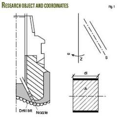
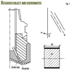
Now suppose that a drillbit is rotating with an unchanged palstance, ω, around its central line, axis z, and the same with central line s of a nozzle. A microelement is set as an research object, with length ds , area A, and mass δm = ρAds. Fig. 1 shows the rotary system and microelement.
Relative coordinate system
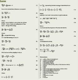
Moving with the drillbit, a relative observer will see the central line of nozzles standing still, and the observer watches fluid flow relative to the drillbit. During the time dt, the microelement has its mass conserved, for it is a closed system (Equation 1).
When fluid is uncompressed, there is ∂ρ/∂ = 0.
For the closed system with mass δm, the first thermodynamic law can be written as Equation 3, which can be rearranged in terms of the change of total energy (Equation 4) and in terms of the total work (Equation 5).
For relative observers, the work of viscous force, τw equals zero when the nozzle is still, and therefore only the pressure of area forces will add work, as shown in Equation 6. Using Equation 2, Equation 6 can be written in the form of Equation 7.
According to the definitions of particle derivative and uncompressed fluid, work of fluid against area forces can be expressed as Equation 8.
For relative observers, inertial forces on fluid include the Coriolis force, 2(ω × Vr), and centrifugal force, ω × (ω × r). The Coriolis force is an apparent force exerted on a body when it moves in a rotating reference frame; it is a by-product of measuring coordinates with respect to a rotating coordinate system. The work of the Coriolis force is 2(ω × Vr)∙ Vr = 0.
Equation 9 shows the work of fluid against the centrifugal force.
In order to discuss easily, we use small letters q, w, and e separately to represent energy from the surroundings (q), work (w), and internal energy (e) of fluid with unit mass. Then from the preceding equations, we derive Equation 10.
When flow is adiabatic and pressure independent on time, DH/Dt = 0. Then the Bernoulli equation at two different sections along the stream line can be shown as Equation 11, where subscripts 1 and 2 refer to two sections along the nozzle axis. If the two sections are the inlet and outlet of a nozzle, then it is easy to get fluid velocity at outlet of the nozzle, V2γ, as shown by Equation 12.
From Equation 12, we can see that if the drillbit is static, namely, ω = 0, Equation 12 will convert into the movement equation for fluid in still nozzles.5
When nozzles rotate with the drillbit, several factors, including the rotation palstance, construction and position of the nozzle, and the pressure difference in the nozzle will directly affect fluid velocity at the outlet. When the displacement difference from the central line of the drillbit of the inlet and outlet is enlarged, fluid velocity at the outlet will increase while pressure difference remains unchanged. Similarly, increasing the pressure difference will also result in a higher flow rate.
It’s necessary for drillbit designers to carefully select construction style and design of nozzles and properly position nozzles on the drillbit in order to get a higher velocity at the nozzle outlet.
All of the preceding equations are deduced from the view of the first thermodynamic law, without concerning the nature of the fluid, so that they are suitable to both Newtonian and non-Newtonian fluid-like slurries.
Absolute coordinate system
In such a coordinate system, the work of fluid with unit mass towards surroundings will have two parts: one is work in relative movement against outside forces, namely Equation 8; the other is in implied movement against external forces, as in Equations 13, 14, and 15. Based on these equations, the first thermodynamic law can be expressed as Equation 16.
We see that Equation 16 is more complex than for the relative coordinate system. If fluid flow is adiabatic and relatively independent on time, there is Equation 17.
Obviously, if the drillbit is still, namely ω = 0, the Bernoulli equation along the stream line can be written as (p/ρ) + (V2/2) = constant.
While the drillbit is rotating, the flow in nozzles must change with time. Additionally, flow velocity at nozzle is difficult to get, for we are unable to learn the branch radial and tangent velocities. Therefore, it is not easy to describe the flow field in an absolute coordinate system.
Although two kinds of coordinate system are used to research the same flow field, work can be simplified greatly by using the relative coordinate system. This also allows us to deduce the flow law, helpful to researches on nozzles and ejecting flow.
Flow analysis for bit design
To design drillbits optimally, it is useful to conduct research on nozzles and ejecting flow. Beginning with the first thermodynamic law, the flow law of fluid in nozzles is deduced and analyzed in both relative and absolute coordinate systems. Although the flow field is complex as a result of rotation, the authors demonstrate that movement equations can be deduced, an advantage of using a relative coordinate system.
The results also show that rotation palstance, construction and position of nozzles, and pressure difference in the nozzles will directly affect fluid velocity at the outlet. In order to get higher ejecting velocities, the authors suggest that the positions of outlet and inlet of nozzles on a drillbit should be considered together with internal pressure difference, while designing a drillbit with nozzles. ✦
References
1. Shen, S., “Drillbit design-key to improve performance,” Petroleum Machinery, Vol. 6 (August 1998), pp. 57-60.
2. Xie, C., “An Optimization Research on Three-dimensional Hydraulics Fields of PDC Drillbit Head,” PhD dissertation, University of Shanghai for Science and Technology, China, 2002, pp. 30-34.
3. Liu, G., Basic Aerodynamics for turbo-machinery; Beijing: Publishing House of Mechanical Industry, 1979.
4. Liu, X., Principle of drill process; Beijing: Publishing House of Oil Industry, 1988.
5. Chen, J., Flow theory of drill liquid; Beijing: Publishing House of Oil Industry, 1996.
6. Pan, W., Engineering Fluid Dynamics; Beijing: Tsinghua University Publishing House, 1988.
The authors
Cuili Xie ([email protected]) is a teacher at the College of Power Engineering, University of Shanghai for Science and Technology, Shanghai. Her research work is concentrated on PDC drillbit hydraulics, fluid engineering, and in other areas. Xie holds a BS and MS in oil and gas storage and transportation engineering from China University of Petroleum. She earned a PhD (2002) in power machinery engineering from the University of Shanghai for Science and Technology.
Ailing Yang ([email protected]) is an associate professor at the College of Power Engineering, University of Shanghai for Science and Technology, Shanghai. Her research work concentrates on PDC drillbit hydraulics, CFD simulations, fluid engineering, and other topics. Yang holds a BS, MS, and PhD in aeronautics from Nanjing University of Aeronautics and Astronautics (1998). She was engaged in postdoctoral research in 1998-99.


