Successful revamp of QP MDEA unit hikes capacity
Successive revamps of Qatar Petroleum’s acid-gas-removal unit (AGR) at the Mesaieed NGL plant increased the unit’s treatment capacity without loss in gas purification efficiency and at minimal capital cost. Favorable features of the initial design of the unit also contributed to this successful revamp.
QP’s AGR removes H2S and CO2 from natural gases from both the North and Al-Shaheen fields. Two parallel trains comprise the unit and were originally designed with Total’s MDEAmax process, based on the use of an aqueous MDEA solvent. The unit has operated at Qatar Petroleum since 1992.
In 1996 a major debottleneck of the unit aimed at increasing its treatment capacity by 31%, to 1.023 bcfd from 780 MMscfd. This increase was accomplished with limited modifications of the existing equipment but resulted in the increase of the CO2 content of the treated gas to 1.3-1.5 vol %, from 1 vol %.
In 2001, a second revamp step shifted the unit to the “energized” MDEA process. This second revamp mainly consisted in changing the solvent formulation, by adding to the MDEA a relatively small amount of a second amine (or “energizer”) to accelerate the CO2 capture. The addition of this “energizer” allowed a reduction of the CO2 level in the treated gas, back to the 1 vol % level.
This article describes the main modifications of both the 1996 and the 2001 revamp steps and provides a brief summary of the overall operation experience before and after revamping.
The NGL-3 plant produces liquid hydrocarbon streams, lean sweet gas, and sulfur. The MDEA technologies, MDEAmax and energizedMDEA, used on these units is a part of the AdvAmine technology portfolio, developed by Total (formerly Elf) and is now commercialized by Prosernat. This gas-sweetening technology portfolio includes several processes, all based on the use of well known widely available amines (DEA, MDEA, and energizers).
The possibility offered by the Adv-Amine portfolio to choose between various solvent types and compositions and also various process configurations gives flexibility and permits meeting any type of process specification. Furthermore, it is also possible to meet significant changes in the process specifications through the life of the unit.
This flexibility has been used on the amine units at Mesaieed for the two revamps of 1996 and 2001.
Total’s amine technology
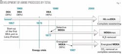
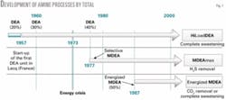
Nearly 50 years ago, the discovery of the Lacq field in southwest of France, containing very sour gas with more than 15 vol %. H2S and about 10 vol %. CO2 has led to the development by SNPA (Société Nationale des Pétroles d’Aquitaine, which became Elf, now Total) of its own amine-based technology. DEA was chosen as the amine, which at that time was a pioneering innovation. SNPA successfully started its first DEA plant in Lacq in 1957. Since then, the company has seen continuous improvements to the technology. Fig. 1 summarizes these improvements.
Main developments were driven by the quest for lower costs and more specifically for lower energy consumption. This trend was specially enforced after the energy crisis in 1973, which resulted in:
- Acid-gas loadings of the solvent (mol acid gas/mol amine), which could be progressively increased, due to the experience and skill acquired in corrosion prevention.
- Parallel increasing progressively the concentration of DEA, up to 40 wt %, which is today considered as a maximum, these two points resulted in what is known today as the HiLoadDEA process.
- Use of selective amine (MDEA) for the removal of only H2S in cases where CO2 coabsorption should be minimized because a liberal amount of CO2 could be slipped to the product gas: MDEA-max.1-3
- Use of MDEA-based processes, with specific additives called “energizers,” for complete gas sweetening, with minimal heat requirements, because of the possibility of partially regenerating the solvent by flash: energizedMDEA.2-8
Today, the AdvAmine technology, which is being licensed by Prosernat in the frame of a partnership between Total, Prosernat, and IFP, is based on considerable industrial knowledge, with more than 110 units built, among them about one fifth are operated by companies in the Total Group.
This knowledge covers not only design skills but also all practical operational issues, such as corrosion control,9 foaming, and solvent degradation. Other specific improvements have also been made, for instance, for high COS removal.
At present, the AdvAmine technology portfolio includes three main processes, all based on the use of non-proprietary chemicals: HiLoadDEA, MDEAmax, and energizedMDEA. A detailed description of the AdvAmine technology portfolio has already been published.10 This article will concentrate on the MDEA based processes in use at Mesaieed NGL plant.
Concept
MDEA is a tertiary amine known to be selective for H2S vs. CO2. The mechanism of this selectivity is based on the difference of kinetics between the reactions of aqueous solutions of MDEA with H2S and CO2, respectively. The reactions can be summarized as shown in the accompanying box 9above) in which R’ represents a methyl group and R ethanol.
The MDEAmax process therefore uses aqueous solutions of MDEA to absorb the H2S selectively from gas streams.
MDEA has other specific advantages over other alkanolamines such as DEA: higher stability and a somewhat reduced specific heat of reactions with CO2 and H2S.
But in order for MDEA-based solvents to be used for complete and simultaneous H2S and CO2 removal, additives called “energizers” must be mixed into the MDEA solution.3 Such energizers are usually primary or secondary amines that will speed up or energize CO2 capture through the reversible formation of carbamate. The accompanying box (above) summarizes the mechanism of such energy enhancement where the energizer is noted as a secondary amine labeled Ez - NH.
| MDEA reactions | ||||
| with H2S | H2S + R’RR N | → | HS- + R’RRNH+ | Fast |
| with CO2 | CO2 + H2O | → | HCO3- + H+ | Slow |
| H+ + R’RRN | → | R’RRNH+ | Fast | |
Both reactions being fast, the HCO3- formation is therefore obtained much more quickly than with the direct hydration reaction between CO2 and water.
Total has patented the application of several different additives used as “energizers” in order to cover various types of industrial applications. Selecting for each application the type and concentration of energizer makes it possible to tailor the removal of CO2 and H2S. This gives a wide flexibility to the technology.
This flexibility is in fact the key feature that has allowed the two revamps at the Mesaieed NGL plant.
Another well-known advantage of MDEA based solvents is that they exhibit absorption curves for CO2 with a significantly lower slope than what is obtained with primary or secondary amines. Thus CO2 can be partially released from the solvent by simple flash.
By this mechanism, referred to as “flash procured regeneration,” it is possible to reduce the amount of solvent sent to the thermal regenerator. This factor can have a considerable impact on treatment costs for gases with high CO2 content and high CO2 partial pressure.7 8 In the extreme case of bulk removal of CO2 only without H2S, the thermal regenerator can sometimes even be eliminated.
Mesaieed plant
The NGL-3 plant, operated by Qatar Petroleum at Mesaieed, is treating 1,023 MMscfd (783 MMscfd capacity was the original design) of sour natural gas and 5,019 tonnes/day (tpd) of condensates from the offshore North field and Al Shaheen field.
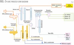
Built by Technip, the plant came on stream in 1992 and consists in two identical parallel trains, each with 50% of the overall treatment capacity. Fig. 2 gives an overall process flow diagram of a complete train.
Condensates are being stabilized and split to produce a stabilized condensate stream that is then sent to oil refinery. The lighter hydrocarbons recovered at the top of the condensate stabilizer, which also contain acid gases, are being mixed with the sour gas that is then fed to the amine units.
The sour gas is sweetened in two parallel amine trains. Downstream of the amine units the gas is dehydrated in two parallel triethylene (TEG) trains (supplied by Prosernat) followed by molecular-sieve dehydration. The dry, sweet gas is then sent to NGL recovery (chiller plus turboexpander plus demethanizer). The lean gas is then compressed and sent to the gas distribution system (GDS) of Qatar, as well as to end users (power stations, petrochemical plants).
| ‘Energizer’ mechanism | |||
| Carbamate formation | CO2 + Ez - NH | ↔ | Ez - NCOO- + H+ |
| Carbamate hydrolysis (energizer is regenerated) | Ez - NCOO- + H2O | ↔ | Ez - NH + HCO3- |
The extracted NGLs from the bottom of demethanizer are then sent to neighboring NGL-1 and NGL-4 plants for further processing.
The acid gas released from the amine units goes to a Claus plant for sulfur recovery. The Claus unit was designed also by Elf (the former Elf proprietary sulfur skills and technologies being today also licensed by Prosernat as AdvaSulf), for a sulfur production capacity of 285 tpd. The produced liquid sulfur is then sent to sulfur forming facilities at the neighboring QAPCO plant, which produces solid sulfur pellets.
Amine units: initial design
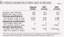
The amine units were initially designed by Elf for the following duty:
The MDEAmax process was then selected, in order to keep the CO2 removal rate at the minimum level required to meet the CO2 specification in the treated gas. The top of the absorber is equipped with multiple solvent injection points to allow adjustment of the CO2 coabsorption and therefore continuously control both the treated gas CO2 specification and the acid gas H2S/CO2 ratio specification.
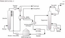
Fig. 3 shows the process flow diagram of the amine unit.
Amine units: first revamp, 1996-97
The amine units started up in 1992.
After a few years of operation, Qatar Petroleum asked Elf specialists to upgrade the units to obtain a significant increase of the gas-treatment capacity, due to increased availability of NFA gas.
The process studies showed that a significant capacity increase-greater than 30%-could be obtained with very few equipment modifications, thanks to several favorable features of the initial design:
- The margins of the original design allowed for about 10% overcapacity.
- The actual H2S content of the feed gas was reduced to 0.66 mole % instead of the 0.924 mole % of the original design; CO2 feed content was also slightly reduced from 2.391 to 2.22 mole %.
- Qatar Petroleum was at that time able to loosen the CO2 specification in the treated gas, which could be increased up to 1.3-1.5 vol %.
- The combination of these two factors allowed treatment of 30% more gas with lower amine flow rate compared with the initial design.
- Consequently, the design of all the equipment pieces in the amine loop (pumps, amine regenerator, so forth) was sufficient and no modification was required there.
- The number of trays in the absorber was sufficient.
- The only limitation to gas flow rate increase was therefore the hydraulic capacity of the absorber. This hydraulic capacity could be increased by replacing the original valve trays by high-efficiency Nye trays (manufactured by Koch-Glitsch LP, Wichita).
Design calculations showed that replacing the trays would result in an actual increase of the absorber hydraulic capacity of about 20%. Combined with an overdesign factor of about 10%, the overall gas-treatment capacity could then be increased by more than 31% from the initial 390 MMscfd up to 512 MMscfd in each train.
After replacement of the trays in the absorber, the actual gas-treatment capacity achieved was the targeted 512 MMscfd. After revamp, the treated-gas H2S content was still well below 4 ppm (vol) and the CO2 content was in the expected range of between 1.3 and 1.5 vol %.
Amine units: second revamp, 2001-02
An ethane-recovery project in the downstream NGL-4 plant required the CO2 content in the treated gas from the NGL-3 plant to be reduced to the initial design of less than 1 mole % from 2001.
The gas treatment capacity of 512 MMscfd achieved during the 1997 revamp needed, of course, to be maintained. In the frame of a revamp study by KBR, Elf as licensor then suggested modification of the solvent composition, shifting the technology from the selective MDEAmax process to the energizedMDEA process.
This shift can be easily achieved without a complete solvent overhaul by a simple addition of a calculated amount of a selected energizer; in the present case, Total selected a secondary amine from among various possible molecules. The type and quantity of energizer must be calculated accurately in order to meet the CO2 specification in the treated gas but also to avoid excessive CO2 removal that would have a negative impact on the operation of the downstream Claus unit.
At that time, the feed design bases were again slightly modified. The new feed H2S content was slightly reduced to 0.466 vol % (instead of the previous 0.66 vol %). The CO2 content was increased to 2.702 vol % (instead of the previous 2.22 vol %). The treated gas H2S specification remained unchanged at <4 ppm (vol).
The combination of increased feed CO2 content and reduced treated-gas CO2 content resulted in the need for an increased solvent flow rate. The additional heat released by this additional CO2 absorption also required to upgrade some of the heat-transfer equipment. As a whole, therefore, the 2001 revamp required the following equipment modifications:
- Duty of rich-lean amine exchanger increased to 24 Mw/29.77 Mw from 19.2 Mw/22.8 Mw (respective summer/winter design figures).
- Lean amine trim cooler duty increased to 4.98 Mw from 4 Mw.
- New dry gas coolers were installed downstream of TEG units.
- Design flow rate of amine booster and feed pumps increased 356 cu m/hr from 323.5 cu m/hr.
- A new coalescing filter was installed at the inlet of the AGR to remove any possible entry in the absorber of liquid hydrocarbons or any other contaminant from the gas. This implementation of a coalescing filter was not directly linked with the shift from MDEAmax to energizedMDEA but it is strongly advised in all present AdvAmine designs, in order to avoid foaming problems in the absorbers.
The implementation of a coalescing filter upstream of the absorber avoids continuous injection of anti-foam in the amine units, resulting in antifoam agent cost savings and less risk of deposits of antifoam degradation products.
Test runs
After the requested equipment modifications, the energizer was injected in the amine loop progressively over several days. During this period, the amine composition and feed treated- gas compositions were monitored.
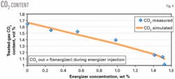
The progressive increase in energizer content in the amine resulted, as expected, in a progressive reduction of the CO2 content of the treated gas. H2S level in the treated gas always remained low (typically in the 1-3 ppm (vol) range).
Fig. 4 plots this reduction of the CO2 content in the treated gas with increased energizer content.
The actual results obtained on the plant have also been compared with simulation results obtained from Total’s proprietary software DESULFO. This software is used for design of Adv-Amine units. It has been developed based on laboratory, pilot plant, and industrial plant results and includes the skills accumulated through the years by Elf (and now Total) on design and operation of amine units.
As Fig. 4 shows, the simulation results match quite well the measured results.
Present operation
Since 2002, the unit has been in operation at the increased design capacity of 512 MMscfd with the energizedMDEA solvent formulation. The amount of energizer is continuously maintained between 1.9 and 2.1 wt %, resulting in treated gas CO2 content of 0.85-1 vol % (H2S being always kept at less than 4 ppm (vol)).
The makeup of energizer needed to keep its concentration around 2 wt % represented under stabilized conditions in 2003 about 2% of the MDEA make-up, so that the resulting chemicals makeup cost remains very low and close to the cost of using generic MDEA.
The overall operation of the unit is therefore good, with only a few minor remaining concerns.These are mostly linked to mechanical issues rather than to the process itself and are in connection with high flash-gas rates. These points are now subjext to specific investigations.
Leaks have been observed on the rich-lean amine plate exchangers. The source of these leaks has been identified as crevices from the existing butyl rubber gaskets. Following vendor recommendation, they have now been changed to EPDM peroxide-cured gaskets.
References
- Blanc, C., Elgue, J. and Lallemand, F. “MDEA process selects H2S,” Hydrocarbon Processing, August 1981.
- Elgue, J., Peytavy, J.L., and Tournier-Lasserve, J., “Recent industrial developments in natural gas sweetening by MDEA,” 18th World Gas Conference, Berlin, July 8-11, 1991.
- Elgue, J., and Lallemand, F., “MDEA based solvents used at the Lacq processing plant,” GPA European Chapter meeting, London, Jan. 18, 1996.
- Elgue, J.,“Elf Activated MDEA: an important improvement in natural gas sweetening processes,” 19th World Gas Conference, Milan, June20-23, 1994.
- Elgue, J., Peytavy, J.L., and Lallemand, F., “The Elf Activated MDEA process: new developments and industrial results,” International Gas Research Conference, Cannes, Nov. 6-9, 1995.
- Elgue, J., “La MDEA Activée, un solvant aux performances modulables,” CEP&M-COPREP, Journées du Pétrole, Paris, Oct. 10, 2000.
- Lallemand, F., and Minkkinen, A. “Highly sour gas processing in an ever-greener world,” 80th Annual GPA Convention, San Antonio, Mar. 12-14, 2001.
- Lallemand, F., and Minkkinen, A., “Processes combine to assist acid-gas handling, reinjection,” OGJ, Jan. 21, 2002, p. 38.
- Bonis, M., Ballaguet, J.P., and Rigaill C., “A critical look at amines : a practical review of corrosion experience over four decades,” 83rd Annual GPA Convention, New Orleans, Mar. 14-17, 2004.
- Streicher, C., Lallemand, F., Minkkinen, A. and Lecomte, F., “A new look at amines: Extending the gas industry ‘workhorse’ to new limits,” 83rd Annual GPA Convention, New Orleans, Mar. 14-17, 2004.
The authors
Ahmed Khaja is head of the process technology division at Qatar Petroleum. He joined QP in 1980 as operation engineer. Since then he has occupied various positions within QP in the operation of gas plants. In 1997, he entered the process technology division first as lead process engineer. He holds a higher national diploma (1994) from the Polytechnic University of Teesside, UK.
Saleh Gumah is lead process technology for Qatar Petroleum’s gas processing department. He holds a BSc (1985) in chemical engineering from the University of Tripoli, an MSc (2000) in natural gas engineering and management from the University of Salford, UK, and a postgraduate diploma (1999) in the management and economics of natural gas college of petroleum and energy studies, Oxford University, UK.
Christian Streicher ([email protected]) has been amine business development manager for Prosernat-IFP Group Technologies since 2001. He was previously research and development project manager at IFP, in charge of the development of gas treatment, sulfur removal, and LNG processes. He graduated from the Ecole Centrale de Paris in 1984 and holds a PhD (1989) in environmental engineering.
Viep Hoang Dinh is amine technology expert and group leader for Total. Having occupied various positions in the Elf and now Total Group, he has 30 years’ experience in gas processing, more specifically in amine gas-sweetening technologies both as developer and user of Elf’s amine processes. He graduated from the Ecole Centrale de Paris in 1972 and obtained his PhD (1976) from Ecole Centrale de Paris.
