Enbridge Energy Co. Inc. has completed a project which demonstrated the validity of external corrosion and internal corrosion direct assessment (ECDA and ICDA) for its pipelines.
The primary goal of the project was to demonstrate that external corrosion direct assessment (ECDA) and internal corrosion direct assessment (ICDA)-performed in compliance with the National Association of Corrosion Engineers (NACE) and Interstate Natural Gas Association of America (INGAA) methodologies-could be used effectively to verify and manage the integrity of nonpiggable and noninterruptible natural gas pipeline segments.
The programs were conducted with in-line inspection (ILI) using high-resolution magnetic flux leakage (MFL) tools and field verification digs. The objective was to receive approval from the Texas Railroad Commission (TRRC) to use direct assessment (DA), where demonstrated to be appropriate. This article describes the steps Enbridge took in the project.
A total of 32 miles of pipe was assessed, and 25 excavations were performed for ECDA, ICDA, and internal inspection validation. The overall results of the study are encouraging and support the use of the DA process. The results validate the use of ECDA and ICDA as integrity verification and management tools when properly applied to appropriate piping systems.
Background
A significant portion of Enbridge’s natural gas transmission pipelines in Texas cannot accept in-line inspection tools because of mechanical constraints, and the pipelines are not considered practical for pressure testing as an alternative because of complications such as associated service interruption.
ECDA was validated by determining if it could discriminate between those pipeline locations in good condition and those requiring repair or mitigation with respect to external coating and/or corrosion damage. The results were validated through a field dig program and an ILI program.
ECDA relies on direct examinations of the pipeline (i.e., bell hole inspections) instead of internal inspection or hydrostatic testing.
A detailed protocol was developed and used for this project. Pipeline operators have historically used a variety of electrical survey tools to manage external corrosion, and ECDA incorporates these tools in the following steps: preassessment, indirect inspection, direct examination, and postassessment.
• Preassessment includes compiling historic and current data to determine whether ECDA is feasible, define ECDA regions, and select indirect inspection tools. The types of data collected are typically available in construction records, operating and maintenance histories, alignment sheets, corrosion survey records, other aboveground inspection records, and inspection reports from prior integrity evaluations or maintenance actions.
• Indirect inspections cover above-ground inspections to identify and define the severity of coating faults, other anomalies, and areas where corrosion activity may have, or may be, occurring in the areas under investigation. Two or more complementary indirect inspection tools are used over the entire pipeline segment under investigation to provide improved detection reliability under the wide variety of conditions that may be encountered along a pipeline right-of-way.
• Direct examinations are performed at the most likely locations to have coating or corrosion damage. This step includes prioritization of indications from indirect inspections; excavation of locations where coating flaws and/or corrosion are most likely; measurement of coating damage and corrosion defects; and damage severity, root cause analysis, and process evaluation.
• Postassessment defines reassessment intervals and assesses the overall effectiveness of the ECDA process and determines reassessment intervals.
ICDA was validated by determining if locations of possible liquid accumulation were associated with internal corrosion. ICDA is a four-step process based on the principle that for dry gas transmission pipelines liquid collects at isolated locations in the pipeline and that it is at these locations that internal corrosion is most likely to occur. Detailed examinations of locations along certain pipelines where an electrolyte (such as water) first accumulates are expected to provide information about the remaining length of pipe.
Preassessment collects essential historic and current operating data about the pipeline, determines whether ICDA is feasible, and then defines ICDA regions. The types of data to be collected are typically available in construction records, operating and maintenance histories, alignment sheets, corrosion survey records, gas and liquid analysis reports, and inspection reports from prior integrity evaluations or maintenance actions.
Indirect inspection covers flow modeling techniques, developing a pipeline elevation profile, and then identifying sites where internal corrosion may be present.
Detailed examination (also termed Direct Examination) includes prioritizing and performing excavations, and conducting detailed examinations of the pipe to determine whether internal corrosion is present.
Postassessment covers analysis of data collected from the previous three steps to determine the effectiveness of the ICDA process and to decide upon reassessment intervals.
The project
The project was carried out by a team of both in-house and third-party experts. The Enbridge staff participation was essential to the project and established the framework for Enbridge to consistently implement future DA programs.
Enbridge’s pipeline system was examined using the ECDA and ICDA preassessment criteria to identify a pipeline segment for validation of the DA process. The selection criteria included the following:
• Regulation by the TRRC.
• Suitability for ECDA.
• Suitability for ICDA.
• Suitability for ILI.
• Minimum affect on customers during the ILI and excavation programs.
An 8-in. pipeline in northeast Texas was chosen as the best pipeline segment to validate the direct assessment process.
ECDA validation
The Enbridge ECDA process was successfully validated through a combination of field verification excavations (direct examination) and ILI validation. Eleven excavations in three DA regions over 26 miles of the 8-in. pipeline validated the process. Eight excavations checked possible anomalies detected during the indirect surveys.
Three excavations evaluated the potential for “missed” anomalies at control sites where no indications were detected during the indirect surveys. These investigations successfully identified 100% of the potentially injurious anomalies.
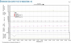
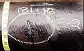
Table 1 lists the locations selected for direct examination. Fig. 1 shows an ECDA survey plot of Indication I-40 that corresponds to Excavation Number E-2. The associated anomaly is shown in Fig. 2. The excavation numbers are not sequential because alternate sites were selected in consideration of access and landowner effects.
In all cases where coating damage or coating degradation was detected, the corrosion was successfully mitigated, the corrosion was no longer active, and the pipe had no measurable wall loss.
Nine excavations of ILI indications of external corrosion were conducted to further validate the ECDA process. In those cases where the ILI tool identified external wall loss not identified by the ECDA process, and excavations were performed for validation, it was determined that all of the corrosion had occurred prior to use of the 8-in. pipe in the IPC Lateral in the Enbridge system.
Field verification of ILI-detected dents, gouges, and minor corrosion with perfectly intact protective coatings; lack of corrosion product in and around pits; and evidence of the coating in the pits, dents and gouges, confirmed that the IPC Lateral pipeline was constructed with reclaimed and reconditioned pipe.
ICDA results also confirmed this suspicion when compared to the ILI internal corrosion features. These conclusions supported the determination that ECDA (and ICDA) are valid for integrity verification.
The results of the ECDA investigation can be summarized as follows:
• The ECDA process identified 239 indications of possible coating or corrosion anomalies. Eight ECDA indications were selected for excavation and used for comparison with three controls.
• All eight ECDA excavations showed coating damage and metal pipe exposure.
• No corrosion was found in four of the eight ECDA excavations; three showed slight corrosion damage and one showed mechanical damage. In the cases where corrosion was found, the total metal loss was less than 10% of the total pipe wall thickness.
• No coating holidays, disbonded coating, or external corrosion was found at any of the three ECDA control excavations.
• The results of the ECDA process were compared with the ILI results. There were nine ILI digs. Seven of those nine were not detected by the ECDA process because there were no coating faults or coating damage present at those sites. The coating was in excellent condition and well adhered to the pipe surface. Dents and slight external corrosion were found at those sites, and there was mastic coating within the corrosion pits and dents.
These observations showed that the indications were present on the pipe surface prior to the application of the actual coal tar coating. The pipe was probably reclaimed pipe that was previously in service and used for the construction and installation of this pipeline.
• One of the nine ILI digs correlated with an ECDA indication showing external corrosion with metal loss.
• One of the nine ILI digs corresponded to an ICDA dig. No coating damage and external corrosion was found. In addition, no ECDA indications were found. These results also supported the ECDA process with respect to external corrosion not being found.
The results of this project support the use of ECDA as a valid external corrosion integrity verification tool and a technically sound alternative to ILI and pressure testing. ECDA was effective for identifying areas of coating flaws and corrosion damage. This was demonstrated by the ability to discriminate between pipeline locations having different conditions with respect to both corrosion and coating damage.
ICDA validation
The Enbridge ICDA process validation compared the results of ICDA with the results of ILI. The results of both integrity verification methods showed that the 8-in. pipeline had not experienced significant internal corrosion associated with episodic upsets of water.
ICDA was performed in accordance with draft NACE Standard TG293 for “Natural Gas Transmission Pipeline Internal Corrosion Direct Assessment (ICDA) Methodology.” ICDA is based on the principle that water (if present) collects at isolated locations in a pipeline and that these locations can be predicted through multiphase flow modeling.
If the locations along a length of pipe that are most likely to accumulate water have not corroded, then other locations along the pipeline less likely to accumulate electrolyte are also unlikely to have suffered corrosion.
No significant corrosion was found at any of the ICDA excavations. This led to the conclusion that significant corrosion in the entire segment was unlikely. Based on historical operating data and pipeline characteristics, five ICDA sites were selected for excavation and examination.
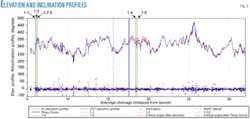
The sites are listed in Table 2 and shown in Fig. 2. Three of the sites were in Region 1 downstream of the pipeline segment start. Two of the sites were in Region 2, as defined by the possible historical input of liquid water at the Piney Grove tie-in (Fig. 3).
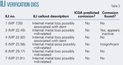
ILI data showed anomalies identified by the ILI vendor as internal metal loss. However, further investigation revealed that most were due to factors other than internal corrosion, e.g., dents or external mechanical damage. From the results of ILI, seven locations were excavated to verify the presence of internal corrosion.
The sites are listed in Table 3. Five locations were incorrectly identified by the ILI tool and had no evidence of internal corrosion. However, internal corrosion was found at two locations, and the sections were cut out for laboratory analysis.
One location (ILI No. 5) had a variation in wall thickness between 0.125 and 0.156 in., which represents less than 20% wall loss. It was considered insignificant.
The other location (ILI No. 3) had several significant internal corrosion pits. However, analysis of the damage raised doubts about the origin and cause of the corrosion. The site was at an isolated location far downstream from any liquid input, and analysis of the defects indicated the corrosion was not active. The location of corrosion is therefore neither consistent with the premise of ICDA nor with ordinary corrosion engineering experience.
The most likely explanation is the corrosion occurred during a time when the pipeline (or that particular section of pipe) was exposed to a different service. Evidence of corrosion in the pipe before installation was found during the ECDA process, which confirmed this as the most likely explanation.
Two other possible causes for the pits were considered. One possibility was that a previously corrosive condition (e.g., extended periods of wet gas) existed for which ICDA cannot be applied. That condition was considered unlikely because damage throughout the pipeline segment would be expected.
A second explanation was that isolated corrosion occurred during the period of corrosion inhibition. This condition is also considered unlikely because it is difficult to justify that corrosion inhibition protected the majority of the pipeline but allowed isolated corrosion at isolated locations far downstream along the pipeline segment.
The ICDA process concluded that internal corrosion from episodic upsets of liquid water in the normally dry gas system did not result in corrosion damage, which was consistent with the results of ILI. Two locations of isolated internal corrosion damage were identified by ILI, but one location was considered insignificant, and both locations are inconsistent with corrosion that would normally be expected in a natural gas transmission pipeline.
ILI validation
An in-line inspection survey of the 8-in. lateral provided data to validate the ICDA and ECDA methodologies. A tool vendor inspected the line segment with a high-resolution MFL tool and a caliper tool. The tool vendor also cleaned and inspected the pipeline and reported the findings.
The ILI results were validated and appropriate actions taken based upon Enbridge’s procedure for its Midcontinent and Gulf Coast systems, “In-Line Inspection Validation of Results.” This procedure describes the process of validating ILI data for gas transmission pipeline segments in the Enbridge system and provides guidance, and the documentation requirements, for the ILI validation process.
The caliper survey reported no geometry or deformation anomalies above the reporting threshold, >0.250 in., or 2.9% of the pipe diameter. No further analysis of the caliper survey final report was carried out.
The MFL results showed that the odometer system became inoperable after about 0.64 miles and remained inoperable for about 4.2 miles. The ILI tool vendor attributed this malfunction to debris in the pipeline, which caused the ILI tool odometer system to lock-up; therefore, survey data between the launch and 5 miles downstream were unreliable.
This loss of data did not affect reference locations outside of this 5-mile segment of the inspection and did not affect the ILI results for validating ICDA and ECDA. There were eight instances where the MFL tool velocity exceeded the acceptable limits of 0.5 and 5.0 mph.
The MFL tool can acquire data up to 15 mph but to maintain the stated accuracy for depth and length manual grading, the MFL tool speed should be maintained between 0.5 and 5.0 mph. These speed excursions, however, had minimal affect on the location accuracy throughout the inspection.
Enbridge’s selection procedures identified nine locations and 30 anomalies for direct examination for validation of ILI results:
• External metal loss, 7 anomalies.
• Internal metal loss, 7 anomalies.
• Internal-possibly associated with a dent, 2 anomalies.
• Internal-possibly mill related, 10 anomalies.
• Possible dent, 3 anomalies.
• Possible dent with associated metal loss, 1 anomaly.
After these excavations, the ILI data were compared with the results produced by the direct examination. The results concluded the following:
• The ILI inspection could detect and report both external and internal corrosion-caused metal loss.
• The first 5 miles of MFL data were lost due to odometer wheel problems. This data loss did not affect the remainder of the inspection, and anomalies were accurately located for the DA validation.
• The MFL final report accurately classified external metal loss, internal metal loss, and dents. The following classifications were determined to be unreliable, based on the correlation between the MFL predictions and the direct examination results:
-Internal metal loss, possibly mill related. The results suggest that the number of internal metal loss anomalies reported was overstated
-The false calls associated with these anomalies may have been a result of debris carryover by the MFL tool from the 4.2-mile section where the odometer wheels locked-up.
• No dent anomalies above the threshold criterion were reported by the caliper survey. However, one dent discovered by direct examination was 0.310-in. deep, which is above the caliper survey reporting criterion of 0.250-in. depth.
• It was concluded that the results presented in the MFL final report and caliper final report can be used to validate the findings of the ECDA and ICDA methodologies.
Reassessment
The postassessment phase of the DA process required the establishment of reassessment intervals to determine the maximum permissible time between integrity assessments.
The processes used for ECDA and ICDA are necessarily different, but when applied to the same pipeline result in defaulting to the more conservative reassessment interval.
Several indications were selected for excavation based on the ECDA results (i.e., aboveground electrical surveys). None of the excavated indications were considered severe and, therefore, none required immediate action (according to NACE RP0502 guidelines).
All indications were considered minor, requiring only monitoring. RP0502 only requires excavation at minor indications in the absence of other severe or moderate indications. Based on this, reassessment intervals will be defined on the basis of scheduled indications that in this case only required monitoring. Two methodologies are presented for establishing the ECDA reassessment interval. RP0502 offers guidance for establishing a conservative reassessment interval based on calculations of the remaining half life of the pipeline. Enbridge has incorporated corrosion-rate monitoring in its direct examination process and therefore will utilize this methodology.
Based on the results of the excavations, indications were selected by comparing critical angles with inclination angles at each ICDA region.
ICDA reassessment intervals may be determined using one or more of the following:
• Reexamine sites at a prescribed frequency to determine or assess growth rate, i.e., monitor site for corrosion growth on the actual pipe.
• Install one or more corrosion-monitoring devices at sites of predicted liquid accumulation based on flow modeling results, and/or at other representative locations.
• Apply a corrosion-rate model based on operating conditions, gas quality, liquid composition, and other key factors.
• The selected reassessment interval must be technically justified and validated by the operator.
The maximum reassessment interval is found by measuring the corrosion growth rate and determining the time for the defects to reach a critical stage requiring immediate action.
Using corrosion rate monitoring, the maximum measured rate of external corrosion was 7 mils/year (mpy) and taken as the most conservative growth rate. In the case of ICDA, the calculated maximum internal corrosion rate in the presence of water-assuming MAOP and a gas quality of 2% CO2, no H2S, and no O2-was 2 mpy.
Since this is lower than the predicted maximum external corrosion rate, the reassessment interval based on external corrosion is shorter; it therefore supercedes the calculated interval based on internal corrosion. It should be noted that if no water exists in the pipeline, the internal corrosion rate is negligible.
The predicted corrosion rate was calculated through an empirical equation based on tests performed under a wide range of simulated pipeline conditions. This model is appropriate to pipeline corrosion characterized by relatively low levels of corrosive gas, low ambient temperatures, and low liquid flow rates.
Other corrosion models developed for high temperature, high flow rate and high-CO2 systems are considered less accurate in typical pipeline environments. Since no H2S exists in the system, general corrosion was used as the basis for predicting the corrosion rate. In addition, the water was considered to be condensed (low dissolved solids) allowing pH to become acidic, but preventing chlorides from playing a role.
Utilizing the methodologies described earlier and applied to the 8-in. IPC Lateral, the reassessment interval for ECDA will be less than 9 years. For the ICDA process, the corrosion rate was determined to be 2 mpy, and the reassessment interval also will be 9 years.
Results
The DA validation project was successfully completed after a total of 12,000 man-hr. That included the preassessment step to identify a candidate pipeline; develop detailed procedures for DA execution and implementation; and perform indirect surveys. It also included modification of piping; complete cleaning pig runs, gauge pig runs, and two intelligent pig runs.
Detailed direct examinations were performed at 25 excavations, and detailed analyses of the results were completed, including the preparation of the final report.
As a result of the validation study, Enbridge has adopted both external corrosion direct assessment and internal corrosion direct assessment for its natural gas business segment and became the first natural gas operator to receive approval from the Texas Railroad Commission (TRRC) to use direct assessment (DA). ✦
The authors
Carl A. Mikkola is superintendent of systems integrity for Enbridge Energy Co. Inc. Mikkola’s department is responsible for pipeline and facility risk management and integrity assessment. He has 13 years of experience in the oil and gas industry as a project engineer, operations engineer, technical services engineer, and senior pipeline integrity engineer.
Mikkola holds a BS in civil engineering from Michigan Technological University and is a Registered Professional Engineer in Texas, Illinois, and Indiana. He is a certified ANSI/API Aboveground Storage Tank Inspector and AWS Certified Welding Inspector. Mikkola is chairman of the API Pressure Vessels and Tanks Subcommittee.
Christina Case is a senior systems integrity engineer with Enbridge Midcoast Energy LP in Houston. She has more than 10 years of experience in the oil and gas industry, including design, construction, and regulatory compliance with Texas Eastern Products Pipeline Co. and Enbridge. She is currently responsible for pipeline risk and integrity management efforts, development of integrity standards and procedures, and implementation of a company-wide information management system. Case holds a BS in mechanical engineering from the University of Kansas and an MBA from the University of Houston.
Kevin C. Garrity is chief operating officer for CC Technologies, a company specializing in corrosion and integrity engineering and research. He has more than 3 years of experience in corrosion and has managed a number of large pipeline and facility integrity projects. Garrity is an active member of NACE International, serving on its board and executive committee. He currently chairs the annual conference program committee and the task group revising the CP criteria contained in RP01-69. He is a graduate electrical engineer from Polytechnic University in New York. Garrity is a registered professional engineer in several states, an NACE certified CP specialist, and an NACE certified instructor.


