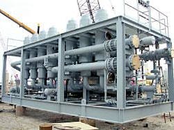
Mallet gas processing facility uses membranes to efficiently separate CO2
The Cynara membrane system at Occidental Oil & Gas Corp.'s Mallet CO2-removal facility, Sundown, Tex., has processed 100 MMscfd of gas with an online availability greater than 99% since 1994 and is being expanded to process an additional 100 MMscfd of gas.
Membranes are reliable process elements for CO2 removal when properly applied. Semipermeable membranes have been in commercial operation for CO2 removal from hydrocarbon gas streams since the early 1980s.
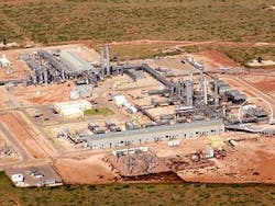
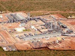
The Mallet CO2-removal facility is being expanded to process an additional 100 MMscfd of gas. The CO2-removal module is circled in the lower right (Fig. 1).
This article reviews the rationale for selecting membranes and the factors contributing to the successful 10-year operation of membranes at the facility.
When properly applied, membranes have a long life and low operating cost. At the Mallet facility, membranes have proven to be a reliable, cost-effective solution during the 10+ years of operation.
Occidental Mallet
Semipermeable membranes have been operating at the Occidental Mallet facility (Fig. 1) since 1994 and are an integral and critical part of that facility's performance. These membranes perform bulk removal of CO2 before downstream treating and significantly reduce the size and cost of the downstream CO2-removal equipment.
Occidental selected membranes for this facility based on installed capital and operating cost for the total CO2-removal facility as well as other operational concerns such as availability, ease of operation, and safety. The alternative was to install two additional methyl diethanolamine (MDEA) units.
The membrane system offered a 30% reduction in operating cost compared to the MDEA system. The membrane system has fewer moving parts and critical controls.
To have a successful facility design, the CO2-removal unit must be considered as a whole, rather than individual systems placed together.
Facility description
The Mallet CO2-recovery facility was built to recover CO2 from associated gas produced from crude that resulted from CO2 injection for enhanced oil recovery. The Mallet plant uses chemical processes for CO2 recovery while using the nearby Slaughter natural gasoline plant for NGL recovery.
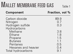
Feed gas to the CO2-removal section contains approximately 90% CO2 and a significant amount of heavy hydrocarbon components (Table 1). Both CO2 and hydrocarbon components are considered products.
Fig. 2 shows a simplified flow diagram of the Mallet facility.
The Mallet plant uses chemical processes in addition to membranes to recover CO2 and sweeten the hydrocarbon gas. It uses membranes, MDEA, and AP-810 (MDEA) to recover and remove CO2 and H2S. The remaining 14-15 gpm of hydrocarbon gas goes to the Slaughter gasoline plant for final NGL recovery.
Membranes are the first step in recovering CO2; they remove about 70% of the total CO2 from the inlet associated gas, which contains about 90% CO2. The next step uses MDEA absorption and flash regeneration. The final step in CO2 and H2S recovery and sweetening uses a conventional AP-810 (MDEA) system.
Hydrocarbon product gas leaving the Mallet facility contains less than 1.5% CO2.
All of the CO2 and H2S is removed at low pressure and is compressed up to 550 psig. The H2S is then selectively stripped from the CO2 using a Selexol process. The CO2 is then dehydrated with tetraethylene glycol and compressed to a final reinjection pressure of 2,500 psig. The CO2 stream leaving the facility contains less than 100 ppm H2S, more than 95% CO2, and less than 25 lb/MMscf of H2O.
Membrane description
Gas purification occurs when the CO2 dissolves into the membrane, diffuses across the membrane wall, and exits on the low-pressure side of the membrane. The rate of CO2 permeation across a given membrane is a function of CO2 composition, feed gas pressure and temperature, membrane material and thickness, and pressure on the membrane's downstream side (permeate pressure).
Permeation of CO2 is not a perfect separation; other components in the mixture will permeate the membrane. The permeation rate of these components depends on the membrane material and particular component.
Fig. 3 shows the relative permeation rate for commonly separated components—the heavier the hydrocarbon component, the slower the permeation rate.
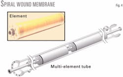
There are generally two membrane configurations, spiral wound and hollow fiber.
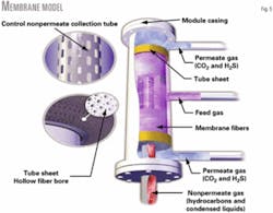
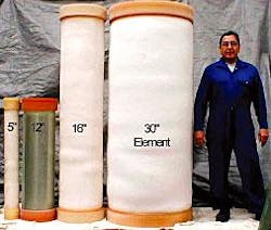
Fig. 4 shows a spiral wound membrane device and Fig. 5 shows a hollow fiber type device. The membranes used at the Mallet facility are Cynara hollow fiber membranes manufactured by NATCO Group Inc. Each membrane element is about 12-in. diameter, 40-in. long, and contains approximately 2,500 sq ft of surface area. The new plant will use 16-in. diameter, 72-in. long membrane elements with roughly 3.5 times the surface area of the 12-in. elements. The membrane fiber is cellulose triacetate.
Fig. 6 shows the actual membrane elements.
Membrane process description
Fig. 7 shows the membrane process flow diagram.
Compressed inlet gas from the field is received at approximately 350 psig. Before entering the membranes, the gas is cooled and dehydrated.
Components that are most detrimental to membranes include liquid water, glycol, amines, lube oils, and heavy hydrocarbon components (C6+). Various membrane materials react differently when exposed to such components; all membrane designs must consider pretreating these components before the membrane.
Pretreatment at Mallet is similar to that employed at many other facilities.
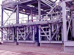
Fig. 8 shows the membrane facility at the Mallet gas plant.
After compression, the inlet gas flows to the membrane pretreatment portion of the plant where it is cooled via cross exchange with product streams from the membrane. The gas is then cooled to about 70° F. in a small propane refrigerated chiller. This controls the amount of heavy hydrocarbons (C6+) entering the membrane.
Large quantities of aromatic components and C8+ components are detrimental to membrane performance. Chilling the feed gas flowing to the membrane allows one to control and limit the composition of these components.
Particular concerns are significant changes in actual inlet composition, changes in future inlet gas composition, and upset conditions. The chiller allows more flexibility and is more forgiving with respect to heavy components that were not indicated in the expected gas analysis.
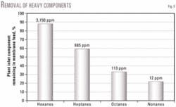
Fig. 9 indicates the effect of removing heavy hydrocarbons by chilling to only 70° F. Only about 12% of the C6 components are removed in the chiller-separator; however, 41% of C7s, 67% of C8s, and more than 75% of C9+ components are removed.
The chiller-separator sends condensed liquid to a stabilizer; the gas is dehydrated in silica gel beds to protect the membrane from liquid water. Membrane performance can be permanently reduced if the membrane is contacted by liquid water, which could occur during upset conditions. The desiccant beds also serve as a guard bed to protect against carryover of treating fluids and heavy hydrocarbon components.
Occidental's existing dehydration unit prior to CO2-removal unit can treat 100 MMscfd (Fig. 8).
After pretreatment, gas flows to the membrane devices where the CO2 is removed in two stages (Fig. 7). No attempt is made to avoid condensation of hydrocarbons on the hollow fiber membrane elements. In fact, due to the amount of CO2 removed, it would be difficult to totally avoid hydrocarbon condensation by simply superheating the gas.
The membrane system is designed to handle hydrocarbon condensation. The hydrocarbon liquid formed on the membranes combines with hydrocarbon liquid from the chiller-separator.
The current feed flow rate is about 102 MMscfd and contains 90% CO2 at 350 psig. The first-stage membranes permeate about 50 MMscfd at 225 psig and the second-stage membranes permeate about 17 MMscfd at 85 psig with an overall CO2 recovery of 70%.
Nonpermeate from the first-stage membranes flows to the second-stage membranes where the permeate pressure is approximately 85 psig. Most of the CO2 is removed in the first-stage membranes at 225 psig. This ability to separate most of the CO2 at a higher pressure significantly reduces the compression required for CO2 reinjection, because such pressure is the suction pressure for CO2 recompression.
Operating history
The Mallet membrane unit was installed in 1995 and has three skids with 90 membrane cases and a capacity of 100 MMscfd. Expansion to be installed in 2005 will double this capacity. Fig. 10 shows the existing membrane skids and the new membrane elements that are being prepared for installation.
Two skids were placed in service in 1995. Table 2 shows the additional membrane elements that the Mallet plant added. Only five elements were replaced in 10 years of operation.
Membrane systems
Users must adhere to strict design considerations to enable successful CO2 separation using membrane systems:
The end user should provide the most complete inlet gas analysis available to the plant design team. The designers should assume that the inlet gas will contain more C6+ components than the analysis indicates. The analysis should include an estimate of what may be injected upstream of the facility, such as corrosion inhibitors and other treating fluids.
The end user should provide a production forecast for the facility. Membrane systems are flexible because membrane devices are easily added or removed as capacity changes.
The design team should consider membranes as a process system integral to the facility. Other process streams in the facility can be sent to or from the membrane system.
The plant design should be a joint effort by the end user, engineering contractor, and membrane supplier.
Mallet membranes
Membranes were chosen instead of other technologies at the Mallet CO2-removal facility because:
Membrane durability lends to fewer replacements and lower operating costs.
These photos show the existing membrane skids (top) and the new membrane skid (bottom) that will be installed in 2005 (Fig. 10).
Membranes recover CO2 at lower partial pressure, which lowers the system operating pressure and reduces total compression.
The CO2 is recovered at relatively high pressure, which reduces CO2 injection compression.
- Membranes use less energy than chemical processes.
- Membranes lower the installation cost due to simple design and modular construction.
- Membranes have no moving parts.
- Membranes reduce downstream equipment size and cost by reducing the CO2 load on the downstream equipment. The tower size in a downstream amine unit can be reduced by as much as 40%, condenser duty can be reduced by as much as 50%, and reboiler duty can be reduced by as much as 40%. This also translates to less electrical and chemical use.
Based on a presentation to the 85th Annual GPA Convention, San Antonio, Mar. 13-15, 2005.
The authors
Gary Blizzard ([email protected]) is a business development manager with Natco Group Inc., Houston. He has nearly 20 years' experience in the energy industry. Previous to joining Natco, Blizzard held positions with Conoco Inc., and Arco. He holds a BS in chemical engineering from Texas A&M University and an MBA from the University of Texas.
David Parro ([email protected]) is chief process consultant with Natco Group Inc., Houston. He has 27 years' experience in the industry, all of it working with membranes for the Cynara Co., which is now part of the Natco Group. He holds a BS (1968) in mechanical engineering from Lousiana State University.
Kirk Hornback is a plant specialist at Occidental Oil & Gas Corp.'s Mallet CO2 recovery plant, Sundown, Tex. He has 28 years of plant experience, working as a roustabout, operator, shift supervisor, and process safety management coordinator. Previous to Occidental, Hornback worked for Amoco Corp. and Altura Energy Ltd.
