Improved method evaluates deflection performance of bent housing motors
Using a downhole motor with bent housing most effectively requires determination of its deflecting performance and designing the bottom hole assembly according to the expected deflection rate.
Drilling with steerable motors is an essential method to build angle and control well trajectory, and bent-housing motors have been popularly used in directional and horizontal drilling for many years.
This article presents an improved method for calculating the deflection rate of bent housing motor assemblies. It provides mathematically precise formulas for reducing the work in processing the calculations. The equations are quite simple, but the precision in calculation is high enough for the calculated results to be in good agreement with those from exact formulas.
This new method involves bent angle position and stabilizer gauge, and reveals the reason why the conventional method shows considerable error. Thus, the calculated results from the method presented are very close to the actual deflection rates.
In addition, the article discusses how to design a bottomhole assembly with a bent housing motor on the basis of the desired deflection rate.
The proposed method applies to both single bent and double-bent motors, such as a double-tilted U-joint. The model and formulas, programmed into computer software, have proven satisfactory for several decades of directional and horizontal wells in China.1
Downhole motors
The oil and gas industry increasingly relies on directional drilling to develop petroleum reserves in environmentally sensitive areas or in restricted surface areas, using multilateral, horizontal, and extended reach wells. Today, two different methods are used for directionally drilling a well: rotary steering and drilling with a downhole motor system. The motor system is designed with a downhole motor and a bent housing. The motor rotates the entire drillstring to drill a tangent section, and turns only the bit to produce a curve or bend.2
There are a number of variants types of bent housing subs, such as fixed-angle types and adjustable types, and most steerable system runs are with bent-housing motors (one or two bends) and stabilization on the motor.
To build angle with this steerable system, the driller orients the tool face toward the high side of the hole. Weight is applied to the bit without rotation of the drillstring. The drillstring slides along the low side of the hole, allowing the bottomhole assembly to build angle.
To drop angle, the driller follows the same procedure, except that he orients the tool face toward the low side of the hole. Therefore, rate of build is achieved in the sliding mode, while in the rotary mode, the achieved angle is maintained.3,4
Drilling with steerable motors is an essential method for building angle and controlling well trajectory, capabilities necessary to the industry. To accomplish steerable drilling, engineers need to calculate the deflection rate of an existing steerable motor and need to design or select a steerable motor assembly on the basis of the expected deflection rate.
History
A number of mathematical and mechanical models have been published around the performance of bottomhole assembly since the pioneering work by Lubinski and Woods. These authors carried out buckling studies on rotary drill strings and addressed such questions as the factors affecting inclination and dog-legging in rotary boreholes and the use of stabilizers in controlling hole deviation.5-7
Most of the models published since, attempt to calculate the side forces at the bit and stabilizers, and the results show that this is an effective approach both in a research environment and in rig-site utilization.
From 1985, the industry began to use three-point geometry to determine the deflection rate of a bent housing motor.8,9 This method has a simple process of calculation, directly describe the relation between deflection rate and tool's structural parameters, and emphasizes the contribution of major parameters to the deflection rate.
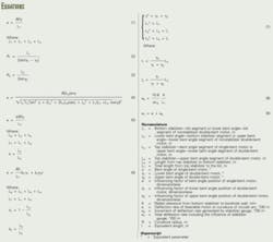
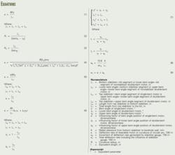
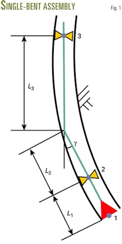
Three-point geometry assumes that a bent housing motor is relatively rigid and directs the bit along a circular arc trajectory that continually minimizes the side force at the bit with its side-cutting capability. According to the definition of segment and rate's unit in this article, Equation 1 (see box) gives Karlsson's formula for calculating the deflection rate of single bent motor (Fig. 1). Nearly 10 years of field experience shows that the conventional three-point geometry usually yields a higher deflection rate than the actual drilled wellbore curvature.
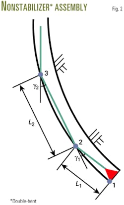
In 1990, Hassen and MacDonald researched the deflection rate of non-stabilizer double bent motor based on the assumption that the three-point arc described by the kick sub, bent housing, and the end of the motor (Fig. 2). This method allows for determination of the radius of curvature that each motor section would fit. Equations 2 and 3 give the deflection rate for the bottom and top motor sections, respectively, presented by Hassen and MacDonald.10
Ideally, the method requires R1= R2 for consistent bottomhole assembly performance. Clearly, in most cases, the two radii of curvature are not equal. Moreover, the method only applies to non-stabilizer double bent motors.
Therefore, it is necessary to improve the conventional geometric methods of evaluating the deflection performance of bent housing motors to be convenient and accurate enough for oil field application.
Single bent assembly
Steerable motor drilling has steadily improved over the past years. The industry now better understands of rig and pump requirements for successful application of these tools. Today, the service industry offers various steerable motors, which are classified for different bit types and rig capabilities. Steerable motor systems can drill a well and control the well trajectory without tripping.
Because of short length, high rigidity, and low weight on bit (WOB), the shape of a bent-housing motor basically determines its deflection rate. A bent-housing motor will tend toward its original rigid shape when it reaches stable mechanical equilibrium. Consequently, it is reasonable to calculate the deflection rate of a bent-housing motor based on its geometrical shape.
Fig. 1 shows the typical single bent assembly of a steerable motor system. As many may know, three points prescribe a circle if they are not in a line. Generally, the drilling community chooses the bit and stabilizers as this kind of control points. As a result, Equation 4 gives the deflection rate of single-bent motor.
Although Equation 4 has a simple process of calculation, compared with other mechanical methods, field engineers may benefit from a further simplification with sufficient precision to meet the practical field requirements.
Because bent angles are tiny (generally no more than 3º), so it is reasonable and effective to simplify Equation 4, while maintaining precision in calculation. Applying cosγ ≈ 1, sing ≈ γ, or sing ≈ 0 to Equation 4 yields Equation 5, which is the applied formula for evaluating the deflection performance of bent-housing motor.
Example 1
To compare the results of the this method with those of Karlsson,8 9 an example calculates the deflection rate of a single bent assembly, given the following input data:
Bent angle: γ = 2º.
Bottom stabilizer (near bit stabilizer)æbit segment: L1 = 1.10 m.
Bent angleæbottom stabilizer segment: L2 = 1.15 m.
Top stabilizer—bent-angle segment: L3 = 4.25 m.
Based on these data, Equation 5 yields k = 14.53º/30 m, but Equation 1 gives k = 18.46º/30 m. It is clear that there is a considerable difference between them. As the influencing factor of bent-angle position is λ: = 0.7870, the deflection rate calculated from the presented method is only 78.70% of that calculated from Karlsson's method.
Compared with the improved method, the conventional method lacks the influencing factor of bent-angle position. The improved method involves the position of bent angle, while the conventional method does not. In fact, the position of bent angle is an important influencing factor on the deflection rate of bent-motor assembly.
Obviously, the influencing factor of bent-angle position is λ <1. In other words, the calculated result given by the conventional method is the maximal deflection rate. That is the reason why the calculated deflection rate is formerly much higher than the actual drilled wellbore curvature.
The research has suggested the following conclusion:
- Deflection rate increases as the bent angle moves toward the bottom stabilizer. When the bent angle arrives at the bottom stabilizer, the single-bent assembly achieves the maximal deflection rate.
- Deflection rate decreases as the bent angle moves toward the top stabilizer. When the bent angle arrives at the top stabilizer, the single-bent assembly invalidates its deflection capability (k = 0).
- Deflection rate is a linear function vs. the value and position of bent angle if the stabilizers keep their positions fixed.
Double-bent assembly
With high deflection rates and steady performance, double-bent housing motors have been widely used to drill highly deviated and horizontal wells. Compared with single-bent motors, they have smaller bent angles and bit offsets to minimize over gauged borehole sections, and run more easily through casing with the same deflection rates.
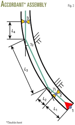
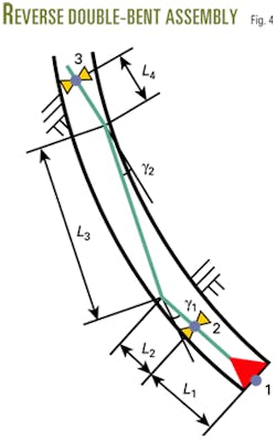
To achieve an explicit deflection rate, the two bent angles of a double-bent motor are in the same plane, and they can bend to the accordant or reverse direction. Figs. 3 and 4 show the two typical assemblies of double-bent motors, respectively.
The bit, bottom stabilizer and top stabilizer form three control points to prescribe a circle, and the curvature of the circle is the reciprocal of its radius. Equation 6 gives the deflection rate of double-bent motor. For a reverse double-bent assembly, the upper bent angle, γ2, should be substituted with a negative value as it bends to the reverse direction of the lower-bent angle.
Example 2
The second example calculates the deflection rate of double-bent motor, given the following input data:
- Lower bent angle: γ1 = 1.5º.
- Upper bent angle: γ2 = 1.25º.
- Bottom stabilizer—bit segment: L1 = 1.15 m.
- Lower bent angle—bottom stabilizer segment: L2 = 0.81 m.
- Upper bent angle—lower bent-angle segment: L3 = 4.27 m.
- Top stabilizer—upper bent-angle segment: L4 = 1.20 m.
From these input data, Equation 6 yields the deflection rate k = 12.48º/30 m for an accordant double-bent motor, and k = 8.62º/30 m for a reverse one.
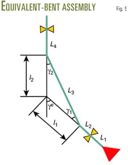
In addition, mathematical conversion can convert a double-bent assembly into an equivalent single-bent assembly, which is valuable for reference to design or select a bent-housing motor. The equivalent single bent assembly simplifies the geometrical relationship of a double-bent motor and makes it easier for calculation and analysis, and it is more convenient to compare the deflection performance between a double-bent assembly and a single one.
Fig. 5 illustrates the geometrical relationship between a double-bent assembly and the equivalent single-bent assembly; Equation 7 gives the equivalent formulas. It is obvious that they mainly describe the value and position of the equivalent bent angle.
Example 3
The third example tests and verifies the correctness of equivalent technique, using the same input data as the second example. First, Equation 7 calculates every equivalent parameters, as γe = 2.75º, L1e = 1.15 m, L2e = 2.75 m and L3e = 3.53 m for an accordant double bent assembly, and as γe = 0.25º, L1e = 1.15 m, L2e = -20.54 m and L3e = 26.82 m for a reverse double bent assembly. Then, substituting the data above into Equation 5 yields k = 12.48º/30 m, and k = 8.62º/30 m respectively. It is obvious that the results are exactly the same with those calculated in the second example. Therefore, the equivalent method and formulas presented are correct and accurate.
For the reverse double-bent motor, the values of l1 and L2e in the third example are negative. The bent angle of the equivalent single-bent motor, that is to say, is located below the bottom stabilizer. Even so, the calculated deflection rate is still correct.
Stabilizer gauge
Results of both theoretical research and field application show that stabilizer gauges, especially for the near bit stabilizer, have a remarkable influence on the deflection performance of a bottomhole assembly. Because the near bit stabilizer is often under gauging, the influence of its gauge on the deflection rate must be taken into account.
Assume that the bottom stabilizer or near bit stabilizer lies on the lower side of borehole. Equation 8 defines the increment of deflection rate generated by stabilizer gauge. Accordingly, Equation 9 provides the total deflection rate of a bent-housing assembly, which applies to both single-bent motors and double-bent motors.
The deflection rate of a bent-housing assembly, particularly sensitive to bottom stabilizer gauge, increases as the radial clearance from bottom stabilizer to borehole wall increases.
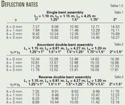
To evaluate the deflection performance of bent housing assembly involving bottom stabilizer gauge, three examples show the proposed method in use. They cover a single-bent motor, an accordant double-bent motor, and a reverse double-bent motor. For convenient comparison, the accordant double-bent motor and the reverse double-bent motor use the same structural parameters. Tables 1-3 show both the given data used and the calculated results.
Assembly design
The selection and design of a bottomhole assembly according to a given deflection rate is a prerequisite during the planning process and drilling. Even though there are many factors influencing wellbore curvature, including borehole geometry, formation conditions, operating conditions, and a number of equipment variables, the bottomhole assembly is a primary and controllable factor.
The presented formulas, assuming that a bent-housing motor is relatively rigid and directs the bit along a circular arc trajectory that continually minimizes the side force at the bit with its side-cutting capability, directly describe and emphasize the contribution of major tools' structural factors to deflection rate. Accordingly, using these formulas is an effective way to select and design a bottomhole assembly.
Research shows that there are five tool structural parameters for a single-bent assembly and seven structural parameters for a double-bent assembly that affect the deflection rate, which relate to stabilizer placement and size, bent-angle value, and location. An engineer can calculate any one of them to satisfy the given deflection rate.
Bent angle, classified in intervals of 0.25º, has only a few optional values available. Through enumerating all values, one can find the best one for a single-bent assembly or the best bent-angle combination for a double-bent assembly to satisfy the expected deflection rate. The calculation process of enumerative technique is similar to these examples.
Because deflection rate is a linear function of bottom stabilizer—borehole wall clearance, it is easy to calculate the value of the clearance. Moreover, because a stabilizer is a standard component, thus one can use enumerative techniques to determine stabilizer gauge.
Most of the tools' structural parameters are continuous variables. One can find the explicit solution to bottom stabilizer bit segment through a sequence of mathematical derivations, and iterative calculation is generally necessary to find the solution to other parameters.1 Table 4 shows some calculated results of bent-housing assembly design.
References
1. Xiushan, L., Shushan, H., and Zou, Y., "Study on the Geometric Build Angle Rate of Steerable Motor," Acta Petrolei Sinica, Beijing, Vol. 25, No. 6, 2004, p. 83.
2. Maidla, E. and Haci, M., "Understanding Torque: The Key to Slide-Drilling Directional Wells," SPE paper no. 87162, IADC/SPE Drilling Conference, Dallas, Tex., Mar. 2-4, 2004.
3. Wisenbaker, B.M., Moser, T.L., Edwards, M.L., and Eggleston, W.H., "Rotary Drilling System Optimizes BHA Performance in Horizontal Austin Chalk Wells," SPE paper no. 38615, SPE Annual Technical Conference and Exhibition, San Antonio, Tex., Oct. 5-8, 1997.
4. Agawani, M., Rahman, S.S., and Maidla, E.E., "A New Approach to Selecting Optimum Bottomhole Assembly Configuration for Any Given Well Trajectory," SPE paper no. 28774, SPE Asia Pacific Oil and Gas Conference, Melbourne, Australia, Nov. 7-10, 1994.
5. Jiazhi, B., "Bottom Hole Assembly Problems Solved by Beam-Column Theory," SPE paper no. 10561, International Petroleum Exhibition and Technical Symposium, Beijing, China, Mar. 17-24, 1982.
6. Walker, B.H. and Friedman, M.B., "Three Dimensional Force and Deflection Analysis of a Variable cross Section Drillstring," Journal of Pressure Vessel Technology, May 1977, p.367.
7. Millheim, K.K., Jordan, S., and Ritter, C.J., "Bottomhole Assembly Analysis Using the Finite Element Method," JPT, February 1978, p.265.
8. Karlsson, H., Brassfield, T., and Krueger, V., "Performance Drilling Optimization," SPE paper no. 13474, SPE/IADC Drilling Conference, New Orleans, La., Mar. 5-8, 1985.
9. Karlsson, H., Cobbley, R., and Jaques, G.E., "New Developments in Short-, Medium-, and Long-Radius Lateral Drilling," SPE paper no. 18706, SPE/IADC Drilling Conference, New Orleans, La., Feb. 28-Mar. 3, 1989.
10. Hassen, B.R., and MacDonald, A.J., "Field Comparison of Medium- and Long-Radius Horizontal Wells Drilled in the Same Reservoir," SPE paper no. 19986, SPE/IADC Drilling Conference, Houston, Tex., Feb. 27-Mar. 2, 1990.
The author
Xiushan Liu ([email protected]) is a professor and deputy director of the Petroleum Drilling Research Institute at Sinopec Corp.'s Exploration & Production Research Institute, a visiting professor at China National Petroleum Corp.'s (CNPC) Key Laboratory of Drilling Engineering, a part-time professor at Daqing Petroleum Institute in China. He has a BS and an MS from Daqing Petroleum Institute and a PhD from the Research Institute of Petroleum Exploration & Development of CNPC, all in petroleum engineering. Liu is a member of SPE.
