Two-step method verifies uprating of older German gas pipeline
A two-step evaluation, using a classical deterministic method and a modern probabilistic one, verified uprating a 35-year-old German natural gas pipeline.
Evaluation in the deterministic redesign focused on such aspects as material properties, defects in the pipeline and welds, fabrication tolerances, and a new calculation of maximum allowable operating pressure (MAOP).
Each component was analyzed, resulting in a ranking list (weakest links of a pressure uprating), a fitness-for-service analysis for the pipeline, and a collection of significant input data for the probabilistic analysis.
The probabilistic assessment analyzed the reliability of the existing system, again identifying the weakest links of a pressure uprating.
One of the basic ideas of this concept is an early identification of the so-called "weakest links" of the system and a definition of adequate activities to overcome these weakest links.
This article presents the main aspects of this concept and discusses the experience gained by its application in a project for a 20% pressure uprating. More detailed information regarding identification of failure modes, limit-state functions, failure consequences, and the adequate estimation of input data will be presented in the future.
Probabilistic analysis
From the economic point of view, pressure uprating of an existing pipeline is an excellent method to increase transport capacity. Such uprating, however, will normally reduce the safety of a pipeline system. The possibility of achieving a pressure uprating on the basis of the existing deterministic standards is, therefore, limited.
Under specific circumstances, probabilistic methods offer an opportunity to analyze the influence of an increased design pressure. In these cases, the probability of failure is calculated for a new MAOP, and this is evaluated with the relevant acceptance values or by comparison with the failure probability of the original system.
As summarized presently, others have successfully used probabilistic methods to assess pipelines and pressure uprating, but these methods are not generally accepted by the responsible supervisory authorities.
ISO proposed a draft for a probabilistic pressure uprating including some limit-state functions for external interference and corrosion.1 Senior described the pressure uprating of an in-service pipeline.2 The probabilistic assessment was performed for 900 km of a 20-year-old pipeline to increase the pressure to 85 bar from 70 bar. The regarded failure modes consisted of external interference, corrosion, and weld defects.
The calculated results from Senior show that external interference made the highest contribution to the total failure probability. Bai and Song presented experience gained from reliability based limit-state design applied in the design and re-qualification of pipelines.3 Their paper discusses the application cases "bursting of corroded pipelines," "dented pipes with cracks," and "buckling of corroded pipelines." Additionally, some values for target probabilities were proposed.
Based on these experiences, Germanischer Lloyd developed a concept consisting of a deterministic and a probabilistic assessment step. The concept has the following advantages, among others:
- Identification of the weakest links of the system as early as possible in the project.
- Provision of a systematic definition of failure modes and identification of the relevant aspects.
- Collection of relevant data for the probabilistic assessment.
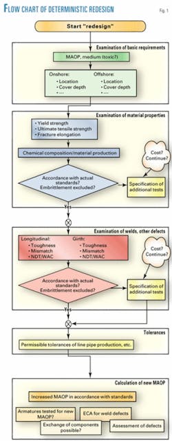
The following discussion describes the flow chart (Fig. 1) of this concept.
Deterministic assessment
The first step of the concept, the deterministic assessment, is designated as deterministic redesign because the pipeline is compared with the main requirements of a state-of-the-art design process. These requirements were assembled under current European standards or internationally accepted procedures and focused on the following aspects:
- Basic requirements.
- Material properties.
- Flaws or defects in the pipeline and the welds (e.g., corrosion or manufacturing defects, girth-weld flaws).
- Fabrication tolerances.
- Calculation of maximum operating pressure.
Fig. 1 shows the main aspects of the deterministic redesign. Each of the boxes in this figure represents a comprehensive flow chart that covers the relevant aspects according to the considered European standards.
The material properties are analyzed on the basis of the material certificates of the line pipe production. These certificates contain such details of chemical composition and material parameters as yield strength, tensile strength, and fracture elongation, as well as the toughness values of base material, weld, and (too seldom) the heat-affected zone (HAZ).
The evaluation of these data by a comparison with the state-of-the-art requirements shows the qualification of the material for pressure uprating, for instance by excluding the risk of material embrittlement. Furthermore, the line pipe material is reclassified into the current standards. In the event that not all relevant details are available, additional testing may become necessary.
To collect all information about flaws in the pipeline inspection reports, the weld qualification tests (WPQ), weld acceptance criteria (WAC), non-destructive testing (NDT), pressure tests, and observations during maintenance must be analyzed. Additionally, the toughness of girth and longitudinal welds must be regarded.
Analysis of the weld details (WAC, NDT) shows whether the present limits are still fulfilled. If not, a fracture-mechanics analysis (ECA) of the maximum defects may be needed to ensure that these nonconformities have no relevant influence on the current MAOP.4
For an ECA, adequate toughness values for the welds are required, which are not always available, especially for older pipelines. In such cases, old material or the extraction of samples from the pipeline and additional material testing may be necessary.
Considering that the extraction of samples can be expensive or impossible, these values should be available at this early stage.
The inspection data provide the details about density, size, and location of corrosion flaws and manufacturing defects. Only in some cases are data about weld defects supplied by inspection tools. After verification of the line pipe material toughness and exclusion of ageing effects, the assessment of these flaws can easily be performed.
Finally, the fabrication tolerances are analyzed in comparison with the currently valid standards to ensure that no higher additional stresses may be present.
All these data collected with the analysis described previously are used for the calculation of a new MAOP for all components or sections of the system under consideration. Finally, a ranking list of all components is obtained.
If only a few elements prevent a pressure uprating, a replacement of these components may be decided to achieve the required pressure increase. In cases where an advantage can be gained from decreasing the applicable safety factor (in accordance with the applicable standards), the minimum new MAOP is higher than the previous value.
The results of the first step of the Germanischer Lloyd concept can be summarized briefly as follows:
- A ranking list of the weakest links is determined.
- A fitness-for-service analysis is performed for the pipeline.
- A significant amount of the input data for the probabilistic analysis is available.
- Confirmation is obtained that the safety concept, material properties, and fabrication procedures comply with modern codes.
New MAOP
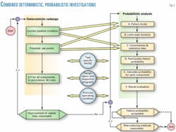
The second step of the developed pressure uprating concept is the probabilistic determination of a new MAOP. During this probabilistic assessment, the reliability of the existing system will be analyzed. The diagram in Fig. 2 shows the main items of the probabilistic investigation and their dependence on the deterministic approach.
The following tasks are integral parts of the probabilistic investigation:
A. Identification of relevant failure modes for the considered system.
B. Determination of limit-state functions for the various failure modes (determination of input parameters).
C. Determination of the main uncertainties and the statistical values of the significant parameters.
D. Definition of the permissible probability of failure Pf,all.
E. Calculation of the current probability of failure Pf,I for each single failure mode and the considered system.
F. Evaluation of calculated failure probability.
G. Investigation of possible risk of failure probability and reduction methods; if the design of the system is changed, a new calculation with changed conditions is necessary.
The basis for Tasks A, B, and C derives from the results of the deterministic approach. Due to the fact that a redesign has been carried out, it is also established that the analyzed system fulfils the requirement of a current design code, taking into consideration all relevant loads and design conditions.
All missing data about relevant design aspects were identified in the redesign step and the effect of the deficiencies can be considered in the probabilistic assessment. It should be pointed out that, therefore, the deterministic redesign should be considered as an essential background for the probabilistic step and that it is one of the most important requirements for the comprehensive probabilistic method. Without this preinvestigation, a probabilistic analysis is, to the authors' understanding, normally not permissible.
The relevant failure modes of the regarded system have to be identified (Task A), taking into consideration the operation conditions during the previous lifetime of the existing pipeline system. Normally, these failure modes are classified into the group's ultimate limit state (ULS), service limit state (SLS), accidental limit state (ALS), and fatigue limit state (FLS).
Typical ULSs are buckling, external interference, corrosion, and weld defects. Limit-state functions for the various groups and failure modes of pipelines have been discussed comprehensively in the literature.1-3 5
The previous operating conditions represent important parameters for the calculation of the failure probability and failure modes. All information about experience with the actual pipeline and its components may be essential to define relevant failure modes and to specify the data required.
Thus, a standardized (electronic) data acquisition and administration system can be helpful and may accelerate this work.
It is recommended that a HazID-like study of the investigated system be conducted by operational experts and design experts from various fields. (HazID: hazard identification for a quantified risk assessment) Because the target of these expert meetings will be used for some specific probabilistic assumptions and validations, a specially developed procedure should be followed during this kind of HazID meeting.
The last three tasks listed on the previous page (E, F, G) deal with the calculation and interpretation of the structural reliability. The calculation of the probability of failure is ideally performed separately for each failure mode because then the influence of each mode (and parameter) is indicated clearly.
For required design data still missing after Tasks A, B, and C have been completed, adequate and conservative assumptions must be introduced. These assumptions may lead to a significant (i.e., unacceptable) probability of failure and, therefore, may have to be improved further. If not, the conservative assumption can be kept unchanged.
After the analysis, the influence of weak links regarding the calculated reliability is demonstrated and can be measured. The interpretation normally leads to an investigation as to how "risk-reducing methods" may increase the safety of the calculated system.
In contrast to the deterministic approach with "unknown safety" based on the failure probability, a magnitude of safety is calculated for each component and can be considered at different points in the future.
Uprating a 35-year-old pipeline
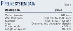
The developed concept was applied for a pressure uprating to 120% of existing MAOP for a section of a 35-year-old onshore pipeline system. The system is about 100 km long and consists of a 30-in. buried trunk line, a station for pressure regulation, gas metering points, and transfer connection to other pipelines and several fittings and valves.
This pipeline is used to transport dry gas at a nearly constant pressure. Table 1 summarizes the basic data of the pipeline.
Fig. 1 shows the redesign step. The significant results of the analysis concern the material properties and the examination of welds.
The results demonstrate that the available specifications for the line pipe material and the results of the material tests regarding the chemical composition were not in accordance with current standards and not sufficiently extensive to exclude the possibility of material embrittlement due to ageing effects.
Together with the operator, it was decided to take additional samples from different pipeline sections, so that it could be verified that the chemical composition indeed complied with current European standards and that embrittlement could be excluded.
The examination of the welds shows that some significant changes in the weld-acceptance criteria have taken place during the last 35 years; for instance, "lack of fusion" defects are not now permissible for onshore pipelines in Germany.
Additionally, old and current standards do not prescribe an NDT frequency of 100% for girth welds of onshore pipelines. Thus, it has to be taken into account that a nonpermissible weld defect may be present in the pipeline in an untested girth weld.
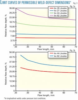
The significance of girth and longitudinal weld defects was analyzed by an ECA. Fig. 3a shows an example of the results of this ECA, in which the limit curves of permissible surface-weld defect dimensions for the longitudinal welds are plotted against the test pressure (1.5.3. MAOP).
The effect of various toughness values, minimum requirements (20 Joules, 27 Joules), as well as minimum (44 Joules) and average values (62 Joules) of the material tests, were considered.
Fracture toughness values were estimated by means of the Charpy energy. The surface defect can be regarded as the conservative case.
As shown, there is a considerable safety margin of the welds because, with a Charpy energy of 44 Joules, a weld defect of 15% depth and 60-mm length will still not propagate during the mill pressure test. For comparison, Fig. 3b plots the results for the new target operating pressure (120% of existing MAOP). In this case, a weld defect of 25% depth and 60-mm length will remain stable for minimum toughness values.
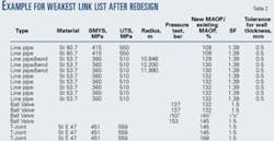
Finally, an MAOP was calculated for various sections, fittings, and valves of the system. Due to the change in international standards of applicable safety factors for onshore pipelines, a slightly higher MAOP was determined. Table 2 shows an example of the results.
For the regarded system, the reliabilities were calculated for both MAOPs to demonstrate the influence of the pressure uprating.
In cooperation with the pipeline operator, the relevant failure modes for the ultimate limit states "leakage" or "rupture" of the system were identified as follows:
- External and internal corrosion.
- Weld defects in longitudinal and girth welds.
- Manufacturing defects.
- External interference.
The following discussion summarizes some of the experience gathered during the analysis.
External and internal corrosion are typically more or less time-variant phenomena of pipelines and are influenced by many parameters. For instance, the external corrosion of an onshore pipeline depends on the corrosion-protection system, soil composition, and surface cladding.
For an operation with dry gas, internal corrosion can be excluded in most cases. If external or internal corrosion takes place, however, the corrosion velocity must be determined. The most accurate approach for this determination is to evaluate the results from several inspections. If only one inspection result is available, the corrosion velocity must be estimated.
Germanischer Lloyd's analysis shows that the importance of corrosion for the probability of failure depends mainly on the existing corrosion flaws (number and dimensions), corrosion velocity, and the inspection tool's accuracy.
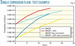
The importance of corrosion and corrosion velocity on the probability of failure will be demonstrated by the test example of a single corrosion flaw with an initial depth of 35% WT, a length of 180 mm, and two different corrosion velocities (100% and 50% of the velocity estimated on the basis of one inspection). Fig. 4 shows that the pressure increase leads to an increase in the failure probability from 10-7 to 10-5.
Further, it is shown that high values for corrosion velocity will lead to an unacceptably high failure probability after a short period, which will necessitate additional action such as new inspection or repair. The optimum date for a new additional inspection may be determined on the basis of the probability analysis.
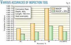
Fig. 5 shows the importance of the accuracy of the inspection tool. The graph plots the probability of failure of a single corrosion flaw of 45% relative depth and 150 mm length for three different accuracies. This study analyzes three statistical values for measurement accuracy, with 80%, 90%, and 99%, respectively, of all measurement errors lying between ±10% WT. According to this, an increase of accuracy of the inspection tool has a significant influence on the probability of failure. For comparison, Fig. 5 plots the influence of a 10% increase in the average for SMYS.
Weld defects in longitudinal and girth welds require special treatment because the number, size, and distribution are not easy to determine. Most inspection tools do not achieve the required accuracy to provide the necessary data.
For all MAOPs below the hydrotest pressure, however, benefits can be obtained from the pressure test of the line pipe in the mill and the hydrotest of the whole system, as long as effects due to cyclic loading can be excluded. For buried onshore pipelines, this should be possible in many cases.
The pressure test demonstrates that all defects in the welds withstand the stress of the pressure test. An additional ECA will often demonstrate that no significant flaw growth may occur during such testing (low cyclic crack growth).
According to the 4th EGIG report, 50% of all gas pipeline incidents that led to a leakage or rupture were caused by external interference.6 This failure mode can thus be regarded as the most important. Interference activities include farming, piling, or ground work.
For the subject pipeline, no long-term observations about kind and frequency of activity are available. The cover depth is greater than 0.9 m. The maximum working depth of a plough is approximately 0.5 m.
Farming activities, therefore, cannot lead to an impact and were excluded. Ground work can reach greater depths than farming activities.
Experimental investigations have shown that the necessary force for leakage or rupture of a pipeline is independent of the pressure in the pipeline.7 According to these investigations, for a buried pipeline 36 in. OD x 0.5 in. WT, a nearly constant impact force of 400 kN is required for the pressure range between 7 bar and 70 bar. Only a very heavy excavator can achieve this force. Normally, therefore, an external interference will cause a dent or a dent with a gouge.
To overcome all problems combined with external interference, the observations summarized in the 4th EGIG report were used for an estimation of the probability of failure. According to this report, for a pipeline between 30 in. and 34 in. OD, an incident frequency of 1 · 10-5 km-1 a-1 was observed. Excavator activities cause 50% of all incidents; thus an incident frequency of 5.3.10-6 km-1 a-1 was used for the analysis.
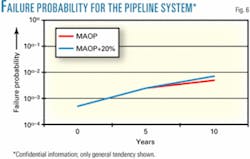
Finally, the time-dependent probability of failure for the regarded system appears in Fig. 6 for the old and the increased MAOP. Because of confidentiality, only the general tendency is shown.
The probability of failure is mostly influenced by the probability of external interference. As explained previously, external interference is not influenced by the MAOP of the pipeline.
After 5 years, the effect of the external corrosion becomes more relevant. At this time, the two curves for the probability of failure relating to MAOP and 120% MAOP start to diverge.
Regarding the effect of the corrosion growth rate, as explained previously, additional or more accurate inspection may keep the probability of failure at an acceptable level. The optimum inspection date can be determined on the basis of the results of the second step of the Germanischer Lloyd concept presented here.
References
1. Annex D of ISO/CD 16708, Petroleum and natural gas industries; Pipeline transportation systems; Reliability based limit state methods. Geneva: ISO, 1999.
2. Senior, G., Hopkins, P., and Francis, A., "Uprating the design pressure of in-service pipeline using limit state design and quantitative risk analysis," 2nd International Onshore Pipelines Conference, Istanbul, 1998.
3. Bai, Y., and Song, R., "Reliability-based limit state design and re-qualification of pipelines." 17th International Conference Offshore Mechanics and Arctic Engineering, 1998.
4. BS 7910, Guide on methods for assessing the acceptability of flaws in metallic structures. British Standard Institution, 1999.
5. Jiao, G., Sotberg, T., and Bruschi, R., "Limit State Based Design Criteria for Offshore Pipelines," Superb Joint Industry Project (Sintef, Det Norske Veritas, Snamprogetti), Sintef, Report No. STF70 F95226.
6. 4th Report Gas Pipeline Incidents, EGIG, 1999.
7. Liu, J., and Francis, A., "New limit state functions for determining the puncture resistance to external force." OMAE 2002, Oslo, 2002.
Based on a presentation to the 6th International Conference on Pipeline Rehabilitation and Maintenance, Berlin, Oct. 6-10, 2003.
The authors
Rainer Hamann ([email protected]) joined Germanischer Lloyd AG in 1995. As a senior structural engineer he is involved in the development of fracture mechanic-based weld acceptance and weld-repair criteria for pipelines, development of assessment procedures for pipeline defects (corrosion), and the deterministic and probabilistic assessment of corrosion flaws in pipelines using analytical and finite element methods. Hamann holds an MSc (1989) of mechanical engineering from Technical University of Brunswick, Germany, and a PhD (1995) from the Technical University of Hamburg-Harburg, Germany.
Thomas Plonski ([email protected]) is a senior structural engineer of Germanischer Lloyd AG where he is responsible for advanced mechanical assessments and structural finite-element investigations for offshore and onshore transportation pipelines, strength and vibration of machinery structures and industrial components, using (classical) deterministic and probabilistic techniques. He joined Germanischer Lloyd in 1990. Plonski holds an MSc (1984) and a PhD (1989), both in mechanical engineering from Technical University of Brunswick.
