Full-scale burst, crack-arrest testing vets X-120 line pipe
Based on a presentation to the 13th International Offshore and Polar Engineering Conference, Honolulu, May 25-30, 2003.
A new high-strength steel with a specified minimum yield strength of 120 ksi has been developed for line pipe applications (OGJ, Dec. 1, 2003, p. 56).1 Because existing specifications were not originally intended for X-120 and no service experience exists for this grade, full-size pipe tests and finite-element analyses were conducted to evaluate structural performance.
This article presents results of burst and fracture-arrest studies and analyses that demonstrate sufficient pressure-containment capacity. For crack arrest, full-size tests evaluated the intrinsic arrestability of the material and the effectiveness of crack arrestors. Although the X-120 pipe did not have sufficient toughness for intrinsic arrest for the conditions tested, tight-fitting sleeve crack arrestors proved effective in stopping propagating fractures.
X-120 evolution
Natural gas demand is growing worldwide. In order to meet future demand, remotely located resources must be developed economically. Often, the high cost of delivering the gas to market eliminates the financial incentive for developing the resource.
One method of transporting natural gas to market is through large-diameter gas transmission pipelines that can improve project economics by reducing the cost of the pipeline. The trend over the years is to use pipe with increased strength so that smaller amounts of steel are required for the line. In addition, the reduced wall thicknesses and corresponding lighter weight can lower construction costs.
In the mid-1990s, ExxonMobil Corp. initiated a program to develop the next generation line pipe steel with 827 MPa (120 ksi) SMYS and 931 MPa (135 ksi) specified minimum tensile strength (SMTS).2 Shortly thereafter, the company entered into similar but independent agreements with Nippon Steel Corp. (NSC) and Sumitomo Metals Industries (SMI) to develop and commercialize X-120 line pipe.
The X-120 pipe is made from TMCP plate and is formed with the UOE process.3-5 (TMCP = thermomechanically controlled processing) A pipe size of 36 in. (914 mm) OD x 0.630 in. (16 mm) WT was the primary focus of the development program and was used for full-scale testing. A few tests were also conducted on other X-120 pipe sizes.
Small-scale laboratory tests, such as tensile tests, Charpy toughness tests, and crack-tip-opening-displacement (CTOD) tests, evaluated the performance of the material throughout the project.3-5 After the project advanced to where the critical material properties satisfied small-scale testing targets, full-size testing verified the structural integrity of the pipe under realistic pipeline loads. The testing also verified finite-element models used to establish new design criteria.
Following are full-size tests conducted as part of the test program:
- Burst.
- Ring expansion.
- Curved wide plate.
- Pure bending.
- Cold bending trials.
- Full-scale crack arrest.
- Crack arrestor (Mojave test).
- Collapse (external pressure).
- Bending + external pressure.
This article discusses only the burst and crack arrest programs.
The primary load in most pipelines is the internal pressure. Design pressures that result in hoop stresses in the pipe as high as 80% SMYS are allowed by many pipeline codes. To provide economic incentive for the higher strength materials, the properties of the X-120 pipe must allow it to be operated safely at pressures resulting in comparable stress levels.
A series of burst tests conducted on X-120 pipe ensured sufficient pressure capacity. Supporting finite-element analysis (FEA) also helped researchers develop a burst limit-state design criterion.
If a failure is initiated in a pipeline, a propagating crack can develop and damage extended lengths of the line. As a result, designing for crack arrest is of utmost importance for gas transmission pipelines. Theories that predict the amount of fracture resistance required to arrest a propagating crack are largely empirical. Due to the unproven general applicability of these theories for higher pressures, rich gases, and new materials, regulatory bodies often require a full-size test to demonstrate crack arrest under design conditions.
Another option for crack arrest recognized by several pipeline codes is the use of mechanical devices known as "crack arrestors."6-8 Due to the complexities associated with modeling a propagating crack and the limited amount of experimental data from arrestor tests, this method of crack arrest also requires large-scale testing to demonstrate the effectiveness of the chosen arrestor for the particular pipe size and operating conditions.9
Burst capacity
Burst resistance is generally associated with the ultimate strength of the pipe material. To maintain structural integrity in the pipe, both the base metal and seam weldment must be able to resist burst failure under design conditions. Standard laboratory tensile tests conducted on the pipe body material and seam weld evaluated the strength performance of X-120 pipe; burst tests verified the burst capacity of the pipe.
null
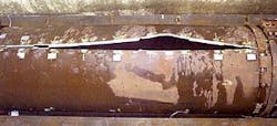
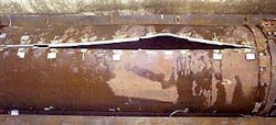
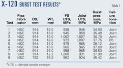
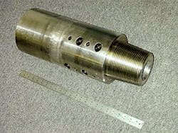
The specimens used to evaluate the burst capacity of the pipe consisted of about 3 m of the X-120 pipe with specially designed, high-pressure caps welded onto each end. ExxonMobil conducted nine X-120 burst tests; SMI independently conducted about 20 burst tests.5 Table 1 lists the manufacturer, geometry, and key properties of the pipes tested by ExxonMobil along with the results. Fig. 1 shows the specimen from Test 7. The fracture surfaces were ductile in all tests.
To analyze the test results, researchers measured the basic material properties of the pipe through a series of small-scale tests. They tested a combination of full-thickness tensile straps and round bars to measure the yield stress (YS; defined as the stress at 0.2% plastic strain) and the ultimate tensile strength (UTS) in the hoop and axial directions. Round bar specimens were primarily used to obtain accurate measures of the YS in the hoop direction and the strength properties of the weld metal.
Several available equations predict the burst capacity of pipe and, in general, apply to failure in the pipe body. The most common estimate is the substitution of UTS for the flow stress (sf) in the following equation:
null
where:
Pb = burst pressure
t = pipe wall thickness
OD = pipe outside diameter
In addition to analytical predictions, detailed FE models simulated the burst tests. The models incorporated the material behavior of the base pipe, seam-weld metal, and the heat-affected zone. Table 2 lists the burst-pressure predictions from Equation 1 and the FE analyses.
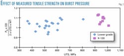
Fig. 2 shows the results from the X-120 burst tests with results reported by Stewart10 on lower grade pipes. The results demonstrate that the burst integrity of X-120 pipe is similar to or better than the burst integrity of lower grade pipe and therefore meets strength-performance requirements.
Fracture testing and analyses also verified pressure containment in the presence of a defect, the results of which will be presented in the future.
Crack-arrest design
Should the structural integrity of a pipeline become compromised, a running ductile fracture can develop and damage extended lengths of a pipeline if not properly mitigated. Two methods of crack arrest have been investigated for the X-120 application: intrinsic arrest and crack arrestors. Full-size testing has determined that successful crack-arrest designs are available for an X-120 pipeline.
As a result, in pipeline design cases whose operating pressure requires the evaluation of crack-arrest performance, crack arrestors can provide a reliable method of ensuring adequate resistance to propagating fractures.
Intrinsic arrest
Traditionally, pipelines are designed so that the toughness in the pipe material can intrinsically arrest a propagating crack. Much research over the past 30 years has focused on determining the required toughness. Several methodologies have been developed and subsequently modified to match results generated through full-scale testing.
Since the approaches are semi-empirical, the appropriateness of these models to new materials and operating conditions outside of the range of those tested is unknown. As a result, full-scale testing remains critical to verify crack arrestability in pipeline designs outside the envelope of conditions previously tested. Recent advances in prediction of crack arrest show promise in application to higher strength steels.11 These theories, however, will also need to be validated through testing before general applicability is proven.
For X-120 line pipe, it was recognized that intrinsic arrest would be very difficult because applications using the new pipe would generally require relatively high diameter-to-thickness (D/t) ratio (> 45) geometries and high operating pressures to take full economic advantage of the new material.1
Because the actual toughness required for intrinsic arrest in the X-120 was unknown, the development program focused on maximizing the toughness while maintaining adequate strength properties. A full-scale crack arrest test (FSCAT) evaluated the intrinsic arrestability of the material.
Target development
Investigators looked at several models estimating the level of toughness required to arrest intrinsically a ductile propagating fracture in an X-120 pipeline. These models fall into one of two categories: a corrected Battelle two-curve model or a crack-tip-opening-angle (CTOA) model.12 These approaches utilize drop-weight tear tests (DWTT) or Charpy V-notch (CVN) tests to evaluate material toughness.
In addition to the two approaches described, ExxonMobil has been developing a crack-arrest prediction capability that incorporates the tearing resistance of the material directly into FEA through a damage-based constitutive model.13 This model is still under development and will require experimental validation to demonstrate its capabilities.
Researchers calculated both CVN values and a CTOA value for arrest in a 36 in. OD x 0.630 in. WT X-120 pipe assuming a pure methane gas at a pressure corresponding to 72% SMYS hoop stress.
The predicted CVN values ranged from 211 Joules to 278 Joules and the CTOA for crack arrest was calculated to be 11°. The CTOA method was not pursued extensively in the development program because measuring the CTOA in the X-120 proved to be very difficult.
Once pipe was developed that produced CVN toughnesses in the range of the predicted requirements, a FSCAT determined the adequacy of the discussed models and the intrinsic arrest capability of the line pipe.
Measurements of toughness were made throughout the development of the X-120 to evaluate and maximize resistance to crack propagation. Researchers performed DWTT, CVN, and CTOA tests to develop an understanding of the material behavior. Table 3 shows the typical measured properties from these tests.
FSCAT Mojave tests
Before performing a FSCAT, researchers conducted smaller, single joint tests to ensure that the propagating fracture would be ductile under conditions expected in the FSCAT. These tests were also used to study crack propagation and ring-off at the girth welds.
The tests were conducted in the Mojave Desert and therefore were named "Mojave" tests. Unlike the more common West Jefferson Test (named after Battelle's West Jefferson, Ohio, site), the Mojave test is pressurized with 100% gas in order to provide sufficient energy to assess the pipe behavior in the presence of a propagating crack.
Researchers conducted four Mojave tests in preparation for an FSCAT. Table 4 summarizes the test conditions, pipe toughness, and results of the tests. Tests 1-3 were conducted on unburied specimens, while Test 4 was buried. Test 4 also included extra weld cap passes to prevent ring-off.
The results of these tests proved the fracture propagated in a ductile manner for the given test temperatures and demonstrated that ring-off could be prevented under FSCAT-like conditions.
After completion of the Mojave tests, an FSCAT evaluated intrinsic crack arrestability in the X-120 material and assessed the models used to determine the required CVN toughness. Centro Sviluppo Materiali SpA performed the test in Sardinia, Italy.
Nine X-120 pipes, including one lower toughness initiator pipe, were arranged in a 90-m test section with two 110-m reservoir sections attached to each end. The CVN toughness of the 36 in. X-120 pipe used in the test ranged from 215 Joules to 278 Joules. The test used lean natural gas pressurized to 20.85 MPa.
A 2 m long, loose-sleeve crack arrestor made from X-65 material was installed at one end of the test section. The crack arrestor was designed according to a Pipeline Research Committee report and was then doubled in length to increase the likelihood of success.14
The FSCAT was conducted on Dec. 12, 2000. Instrumentation included timing wires, thermocouples, pressure transducers, and strain gauges. The gas test temperature was about 12º C.
null
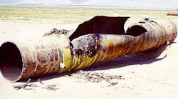
The initiated crack propagated to both ends of the test section, indicating insufficient toughness in the pipe for intrinsic arrestability at the prescribed test conditions and the ineffectiveness of the loose-sleeve crack arrestor. Fig. 3 shows posttest photos.
The fracture surfaces were 100% ductile and the fracture speed ranged between 280 and 350 m/sec. The results demonstrated that the reviewed models based on CVN testing do not correctly predict the toughness required for intrinsic arrest in X-120 line pipe.
Crack arrestors
The other method of crack arrest investigated in the X-120 development program was the application of crack arrestors. Pipeline codes recognize the use of such devices.6 7
The most dominant application of crack arrestors has been in CO2 lines for which the volatile nature of the gas makes intrinsic arrest difficult to achieve.15 16 Similar devices are also used in offshore pipelines to stop propagating buckles. In fact, sleeve buckle arrestors installed on the FLAGS (Far North Liquids and Gas System) gas pipeline in the North Sea were evaluated to determine their effectiveness as crack arrestors.17 Results from the FLAGS tests indicated that the installed arrestors were effective and therefore would minimize pipeline damage in the event of a rupture.
Initial screening of the X-120 line pipe for several applications indicated that the required toughness would be larger than readily achievable in the material. Based on these findings, researchers recognized the implementation of crack arrestors as a necessary design option for implementation in high-pressure applications.
In light of the high toughness requirements and the FSCAT result, two additional tests used the Mojave test setup discussed earlier to evaluate crack arrestors further.
Crack-arrestor design, test
In general, three categories of crack arrestors are available: loose sleeve, tight-fitting sleeve, and integral.
Researchers considered each for crack arrest in X-120. From these options, they determined tight-fitting sleeve arrestors and integral arrestors to be viable for an X-120 pipeline. They then evaluated several tight-fitting sleeve designs with full-size tests. No tests on integral arrestors have been performed.
Two Mojave tests evaluated four tight-fitting sleeve crack arrestors. Each arrestor encircled the pipe and was placed over a thin layer of grout to ensure an even distribution of loading between the arrestor and pipe. Table 5 lists the arrestors used in each test and the test conditions.
Researchers determined the length of the test specimens needed to ensure that the propagating crack encountered the arrestor before being affected by a reflected decompression wave. Burial of the specimens and restraint by concrete blocks at the ends to prevent excessive movement of the pipe better simulated pipeline conditions. Researchers performed the tests at ambient temperatures because proof of ductility was not a test objective.
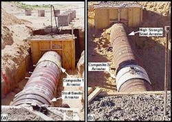
In Test 1, one end of the pipe was fitted with four steel bands made from A36 steel. Each band was about 50 mm thick and 230 mm long. The bands were spaced on 100-mm intervals on the pipe
null
On the other end of the test specimen was a fiberglass composite arrestor measuring about 32 mm thick and 914 mm long. Fig. 4a shows the arrestors on the pipe. Lean natural gas used in this test closely simulated actual service conditions.
In Test 2, a high-strength steel (HSS) crack arrestor was tested on one end of the pipe, and a composite arrestor design was tested on the other end. This composite arrestor came from a different manufacturer than the Test 1 arrestor. For the steel arrestor, a 36-in. section of the X-120 pipe was cut and welded over the pipe to form a tight fit.
The wall thickness of this arrestor was the same as the pipe: 0.630 in. The composite arrestor in this test was 36 in. long and 0.985-in. thick. Fig. 4b identifies the arrestors for Test 2.
null
Both arrestors achieved crack arrest in Test 1 (Fig. 5). In the second Mojave crack-arrestor test, the HSS sleeve successfully stopped the crack while the composite arrestor was completely severed and did not stop the crack.
Test results
Data obtained from the Mojave tests show the applicability of the results to actual pipeline scenarios.
The timing wires installed on the specimens confirmed that the crack speeds were similar to those recorded in the FSCAT. In addition, the data provided evidence that the reflected decompression wave did not interfere with the propagating crack before reaching the arrestors.
Both arrestors in Test 1 (Fig. 5) achieved crack arrest. In the second Mojave crack-arrestor test, the HSS sleeve successfully stopped the crack, while the composite arrestor was completely severed and did not stop the crack. These results demonstrate that the implementation of properly designed tight fitting crack arrestors is a viable alternative to intrinsic crack arrest.
References
1. Corbett, K.T., Bowen, R.R., and Petersen, C. W., "High Strength Steel Pipeline Economics," 13th International Offshore and Polar Engineering Conference, May 25-30, 2003, Honolulu.
2. Fairchild, D.P., Macia, M.L., Papka, S.D., Petersen, C.W., Stevens, J.H., Barbas, S.T., Bangaru, N.V., Koo, J.Y., and Luton, M.J., "High Strength Steels – Beyond X80," International Pipe Dreamer's Conference, Nov. 7-8, 2002, Yokohama.
3. Asahi, H., Hara, T., Sugiyama, M., Maruyama, N., Terada, Y., Tamehiro, H., Koyama, K., Ohkita, S., Morimoto, H., Tomioka, K., Doi, N., Murata, M., Ayukawa, N., Akasaki, H., Fairchild, D.P., Macia, M.L., Petersen, C.W., Koo, J.Y., Bangaru, N.V., Luton, M. J., "Development of Plate and Seam Welding Technology for X-120 Linepipe," 13th International Offshore and Polar Engineering Conference, May 25-30, 2003, Honolulu.
4. Asahi, H., Tsuru, E., Hara, T., Sugiyama, M., Terada, Y., Shinada, H., Ohkita, S., Morimoto, H., Doi, N., Murata, M., Miyazaki, H., Yamashita, E., Yoshida, T., Ayukawa, N., Akasaki, H., Macia, M. L., Petersen, C. W., Koo, J.Y., Bangaru, N.V., Luton, M.J., "Pipe Production Technology and Properties of X-120 Linepipe," 13th International Offshore and Polar Engineering Conference, May 25-30, 2003, Honolulu.
5. Okaguchi, S., Makino, H., Hamada, M., Yamamoto, A., Ikeda, T., Takeuchi, I., Fairchild, D.P., Macia, M.L., Papka, S.D., Stevens, J.H., Petersen, C.W., "Development and Mechanical Properties of X-120 Linepipe," 13th International Offshore and Polar Engineering Conference, May 25-30, 2003, Honolulu.
6. "Oil and Gas Pipeline Systems," CSA Z662-99. Etobicoke, Ont.: Canadian Standards Association, 1999.
7. "Gas Transmission and Distribution Piping Systems," ASME B31.8. New York: ASME, 1999.
8. "Offshore Standard OS-F101: Submarine Pipeline Systems," Hovik, Norway: det Norske Veritas, 2000.
9. Papka, S.D., Stevens, J.H., Macia, M.L., Fairchild, D.P., and Petersen, C.W., "Full-Size Testing and Analysis of X-120 Linepipe," 13th International Offshore and Polar Engineering Conference, May 25-30, 2003, Honolulu.
10. Stewart, G., Klever, F.J., and Ritchie, D., "An Analytical Model to Predict the Burst Capacity of Pipelines," 13th International Conference on Offshore Mechanics and Arctic Engineering (ASME), Feb. 27-Mar. 3, 1994, Houston.
11. Rudland, D.L., Wilkowski, G., Wang, Y.-Y., Horsley, D., Rothwell, B., and Glover, A., "Investigation into the Use of a Single Specimen for the Determination of Dynamic Steady State Propagation Resistance in High Toughness Line-Pipe Steels," 4th International Pipeline Conference, Sept. 29-Oct. 3, 2002, Calgary.
12. Kanninen, M.F., Leung, C.P., O'Donoghue, P.E., Morrow, T.B., Popelar, C.F., Buzzichelli, G., Demofonti, G., Hadley, I., Rizzi, L., and Venzi, S., "The Development of a Ductile Pipe Fracture Model," Arlington, Va.: AGA Pipeline Research Committee, 1992.
13. Pokutylowicz, N., Luton, M.J., Petkovic, R.A., Nemes, J.A., and Yue, S., "Simulation of Dynamic Ductile Failure in Pipelines," 3rd International Pipeline Conference, Oct. 1-5, 2000, Calgary.
14. Wilkowski, G., Scott, P., and Maxey, W., "Design and Optimization of Mechanical Crack Arrestors for Pipelines," NG-18, Report No. 134, Arlington, Va.: AGA, 1983.
15. Marsili, D.L., and Stevick, G.R., "Reducing the Risk of Ductile Fracture on the Canyon Reef Carriers CO2 Pipeline," 65th Annual Technical Conference and Exhibition (SPE), Sept. 23-26, 1990, New Orleans.
16. Boecker, C., "Large Growth Seen for Carbon Dioxide Pipelines," Pipeline Underground Utilities Construction, Vol. 39 (1984), No. 6, pp. 4, 6, and 22.
17. Hayes, D.J., and Lux, M.D., "Full Scale Crack Arrest Test and Arrestor Device Performance for the Flags Gasline," 54th Annual Fall Technical Conference and Exhibition (SPE), Sept. 23-26, 1979, Las Vegas.
Crack-arrestor specimens for Test 1 (left) and Test 2 await the start of testing (Fig. 4).
The authors
Scott D. Papka ([email protected]) is currently a research specialist at ExxonMobil Upstream Research Co. He has addressed design and fracture issues for the high-strength steel line pipe development program since joining the company in 1998. Papka holds a BS in aerospace engineering from Wichita State University, Wichita, Kan., and an MS and PhD in engineering mechanics from the University of Texas at Austin.
John H. Stevens currently works with the wells and materials division of ExxonMobil Upstream Research Co. He joined the company in 1998 and has held research positions in high-strength pipeline steel and downhole tubular integrity. Stevens holds a BS in metallurgical engineering from Michigan Technological University and an MS in materials engineering from Rensselaer Polytechnic Institute.
Mario L. Macia is a research specialist for ExxonMobil Upstream Research Co. Since joining the company in 1996, he has worked on the development of materials and welding technology for X-120 pipelines. Macia holds an MS and PhD from the Georgia Institute of Technology and a BS in materials science and engineering from Rice University.
Douglas P. Fairchild works in the special projects division of ExxonMobil Upstream Research Co. He joined the company in 1982 and his areas of expertise include physical and mechanical metallurgy, welding engineering, fracture mechanics, and nondestructive evaluation. Fairchild holds BS, MS, and PhD degrees in welding engineering from the Ohio State University.
Cliff W. Petersen has, since 1995, coordinated the high-strength steel development project for ExxonMobil Corp., which he joined in 1976. He worked 1974-76 for Westinghouse at the Bettis Atomic Power Lab performing research in support of the US Navy's nuclear program. Petersen holds a BS in mechanical engineering from Marquette University and an MS and PhD in ocean engineering from the University of Rhode Island.
