High-capacity trays hike demeth capacity, efficiency at two Middle East gas plants
Replacing conventional valve trays with high-capacity trays in six demethanizer columns at Saudi Aramco's Shedgum and 'Uthmaniyah gas plants eliminated a liquid load restriction in the column top section.
This allowed the top section of the column to handle 50% additional liquid load compared to the previous maximum load without deterioration of the column performance. With the new trays the columns have also shown improved separation efficiency that resulted in a 3-4% increase in NGL production.
The combination of these two effects produced a payback period, on the cost of the revamp, of less than 1 month. The new trays were installed on existing tray supports without additional internal welding. Removal of the old trays and installation of 18 high-capacity trays for one column took 10 days during a scheduled shutdown.
Gas plants
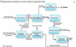
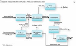
The Shedgum and 'Uthmaniyah gas plants are two identical plants capable of processing up to 2.4 bscfd of associated sour gas produced from crude oil separation operations and nonassociated sour natural gas (Khuff gas).
Conditioning of the sour-gas streams received in both plants removes any liquid condensate carried with the gas and then treatment with diglycolamine (DGA) solution removes acid gas. Compression of the sweetened gas and chilling it in a propane-ethane cascaded refrigeration system recovers NGL (C2+) and methane-rich sales gas.
NGL is then pumped to other Saudi Aramco liquid fractionation facilities on the east and west coasts of Saudi Arabia for further fractionation into petrochemical feedstocks and export sales. Compression of the residue gases, produced in association with NGL recovery, sends them into the country's sales gas pipeline network. Fig. 1 shows the process configuration at both plants.
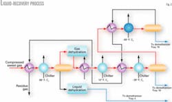
In each plant, NGL is recovered in four identical liquid-recovery modules. In each module, the sweet compressed gas stream is cooled, dried in molecular sieve beds, and then cooled and chilled to –37° C. (–100° F.) with propane and ethane refrigerants.
The liquid recovered by the chilling process collects in three separators and moves in three separate feed lines to a demethanizer column in which NGL is recovered from the bottom and residue gas from the top. This low-pressure residue gas, along with the final ethane chiller separator high-pressure residue gas, forms the plant sales-gas production.
Fig. 2 shows the liquid-recovery process in both plants.
Original demethanizer
Each plant has four identical demethanizers. Each was originally equipped with 18 conventional two-pass valve trays (Koch FlexiTray) and one chimney tray. The top section of the column is 1.8 m (6 ft) nominal diameter equipped with nine single pass valve trays. The bottom section is 2.9 m (9.5 ft) in diameter equipped with nine two-pass trays.
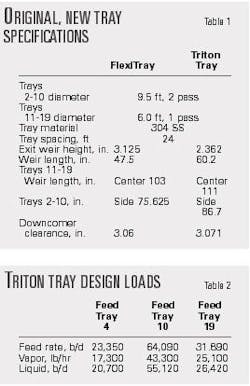
Table 1 shows the design specifications of the original and new trays.
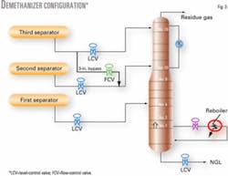
As Fig. 3 shows, the demethanizer receives three liquid feed streams from the upstream chilling facilities. The top section of the column, which includes Tray 19 down to Tray 11, receives liquid feed on Tray 19. Operating history indicated that the top section is limited to about 21-23,000 b/d of the final separator liquid.
As the demand for sales gas and NGL has continuously increased, the plants' operating capacities have been increased to satisfy this demand. At elevated feed rates, the top section of the demethanizer columns flooded.
It has been recognized in both plants that at module feed rates of about 385-400 MMscfd of liquid-rich associated gas, the performance of the demethanizer deteriorated. At these rates, the original Koch FlexiTrays in the top section (Trays 19 to 11) could not hydraulically handle all the liquid recovered in the third separator.
Table 2 shows that tray hydraulic calculations indicated the top section exhibited jet and downcomer flooding. In reality, at elevated module feed rates, the column experienced a rapid increase in pressure drop across the top section, combined with an excessive loss of ethane and propane production to the overhead gas.
These effects are typical of a fractionation column flooding.
Flooding in the top section prevented the demethanizer from achieving satisfactory separation at the required load. An innovation bypass line was added (Fig. 3) to enable the column to handle higher feed rates without flooding by transferring some of the third-stage liquid to the second separator's feed line.
While this line resolved the downcomer flooding problem and minimized propane entrainment when operating at high liquid feed rates, it reduced the column's internal reflux on the top trays and increased the liquid load on the bottom trays. The overall effect was a lower than optimal ethane and propane recovery.
Tray design limits
Fig. 4 shows a conventional two-pass tray in which liquid flows down the column through downcomers, while vapor flows up through the active bubbling area. Flooding occurs if the active area or the downcomers are not capable of handling the operating vapor and liquid rates.
The limitations of conventional tray designs and the characteristics of the different design options of high-capacity trays are discussed elsewhere.1-3 Hood stated that most columns in gas plants have high liquid loadings due to elevated pressures.4
As a result, the design of conventional trays in gas plants normally has large downcomers to handle high liquid loads. Typically, the downcomer top area accounts for 15-25% of the column cross-section area, leaving as little as 50% for active bubbling area. This may reduce the tray's vapor-handling capacity considerably.
A large conventional downcomer also reduces the tray's flow-path length, which limits the liquid-vapor contact time, compromising tray efficiency and possibly requiring higher rates to meet the desired fractionation. Further, conventional tray vapor capacity drops rapidly with increasing weir loading (weir load being a measure of the amount of liquid flowing over a unit of weir length, gpm/in. of weir).
Greater weir load increases the liquid froth height on the tray, which diminishes the disengagement space between trays and hence reduces the capacity.
In summary, using traditional tray design for high liquid loads, both high weir loads and large downcomer combine to diminish the tray's vapor handling capacity. To increase the vapor-handling capacity of a tray, the active area needs to be increased. To do this, however, with a conventional tray normally results in loss of downcomer area, which is not normally possible due to the necessity for large downcomers to handle the high liquid loads.
Therefore in design of a high-capacity tray, consideration needs to be given to improving the downcomer's capacity, in addition to providing a contact device on the tray deck capable of effectively handling the increased vapor traffic.
High-capacity trays
High-capacity trays increase column vapor and liquid capacity by increasing the active bubbling area, increasing downcomer capacity, decreasing weir loading, and reducing hydraulic gradient.
Increasing active bubbling area can be achieved by modifying the area under the downcomer, which remains dead in conventional trays. This can be achieved by either sloping the downcomers from top to bottom or truncating the downcomers above the tray deck and making the area under it active. While both mechanisms increase the active bubbling area, the heavily sloped downcomers maintain the downcomer height, which maximizes liquid handling flexibility.
Increasing downcomer capacity can be achieved by providing large enough downcomer top area to allow the entrained vapor in the liquid leaving the tray to disengage and flow out of the downcomer, thus avoiding downcomer choke flood. This occurs when the rate of liquid entering the top of the downcomer is too high to allow entrained vapor to disengage.
As a result, the downcomer chokes with liquid and vapor, and when it does the liquid level on the tray deck builds up and the column floods. Also, downcomer capacity can be increased by providing low-pressure-drop directional valves or perforated holes (sieve decks) that reduce the tray's pressure drop and lowers downcomer backup.
Decreasing weir loading can be achieved by increasing the weir length, which decreases the liquid height over the weir for a given liquid load. This will result in reducing the liquid froth height on the tray and provide enough disengagement space between trays and hence increase tray vapor capacity and downcomer capacity.
Liquid gradient provides the driving force to push liquid across the tray's flow path length. Minimizing liquid gradient on the tray allows pushing the liquid uniformly across it from inlet to outlet resulting in more uniform vapor flow rate through the active area. This can be achieved by replacing conventional valves with specially designed contacting devices that minimize the relatively liquid flow restriction associated with conventional valves.
For effective high-capacity tray design, however, other important features need to be considered. These include the distance between the downcomer bottom edge and the tray deck, liquid height in the truncated downcomer, direction and momentum of the vapor rising through the active area, and last but not least the dynamic seal of the tray.
In some cases, downcomer and weir loading problems of multipass trays can be alleviated by replacing the trays with multiple downcomer trays (OGJ, Apr. 3, 1978, p. 72).5
New design
Simulation of the liquid-recovery process determined vapor-liquid loads at a future average feed rate of 420 MMscfd of sweet gas. Table 2 shows the future vapor and liquid loads on the three feed trays of the demethanizer. On that basis, the tray supplier was requested to design new trays and internals to handle a maximum flow rate of at least 10% greater than the loads indicated in the table.
Simulation and hydraulic calculations that use future loadings indicated that replacement of FlexiTrays with high-capacity trays would eliminate the flooding at elevated feed rates and maintain the tray separation efficiency.
null
From various commercially available designs and based on Saudi Aramco's competitive bid process, Triton High-Capacity Tray designs were selected for piloting on one demethanizer at Shedgum gas plant.
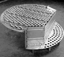
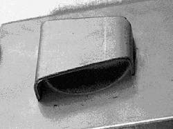
As with other available commercial designs, Triton high-capacity trays provide the high-capacity feature of a truncated downcomer design to increase the active bubbling area (Fig. 5). These trays also replaced the conventional moving valves with proprietary Provalve fixed valves.
These valves have a unique fixed shape that promotes forward-lateral momentum of the vapor through the bubbling area of the trays. The shape and orientation of the fixed valve have been optimized to provide uniform tray capacity for a given tray geometry. This allows greater vapor flow through the column and therefore more hydraulic capacity.
In addition to increasing the hydraulic capacity, extending the active bubbling area beneath the downcomer increases the effective flow path length.5
Because the area under the downcomer contains contacting devices, liquid-vapor contacting begins as soon as liquid leaves the truncated downcomer. As such, Triton tray design provides significantly increased capacity without any loss in tray efficiency.
In addition to the truncated downcomer and proprietary valve design, the new trays were designed with expanded downcomers to provide greater liquid carrying capacity.
And, as Table 1 shows, the weir height was shortened and weir length was increased to provide less weir loading. The downcomer clearance was also slightly increased to allow more space for vapor liquid disengagement underneath the truncated downcomer.
Installation
The mechanical design of the new trays had to consider Saudi Aramco's design requirements that no weld attachments to heat treated coded columns be allowed. This is due to the fact that stress relieving of the shell would be required afterwards.
As a result, the new tray design provided specially designed downcomer adapters that allowed the reuse of the existing bolting bars to fit the new trays without any hot work on the vessel shell. This allowed tray-to-tray replacement without any modifications to the existing tray supports. The existing chimney tray and seal pan were re-used because they were adequate for future loads. The trays were also manufactured from thicker than standard material to provide resistance of an uplift pressure of about 1.5 lb.
During a scheduled plant turnaround and inspection, 18 Triton high-capacity trays were installed in the demethanizer. In addition, a new feed pipe was installed on the main nozzle of Tray 10.
Operating the column for almost 20 years without this feed pipe may have contributed partially to hydraulic problems that were experienced. The mixed-phase feed entering the column at high velocity could entrain liquid up into the top trays with the flashing vapor and force liquid back up in the downcomer at the opposite side of the column to the nozzle.
It was also necessary to modify the existing configuration of the feed pipes on Trays 4 and 19 to accommodate the impact of increasing liquid loads and providing uniform vapor-liquid distribution on the tray deck.
Tray performance
Commissioning of the new trays took place with the 3-in. bypass valve fully closed. The column's hydraulic performance significantly improved, compared with the performance with the original trays. At feed-gas rates to the unit ranging from 300-400 MMscfd of 100% associated gas, the top section of the column showed a significant reduction in pressure drop and increased NGL production.
Therefore, a test run was conducted to evaluate and confirm the performance of the column at higher liquid loads. The flow rate to the unit, which was 100% sweet associated gas during the time the test was being conducted, was incrementally increased up to 480 MMscfd with the liquid bypass valve to Tray 10 fully closed.
The performance benefits of the new trays were evaluated by comparing the performance history of the old FlexiTrays with the results of the test run.
The analysis of the data revealed the following:
Hydraulic performance. The high-capacity trays eliminated the demethanizer's top section hydraulic constraint experienced with the old trays when the liquid rate to the top tray exceeded 21-23,000 b/d. With the new trays, the top section could handle liquid loads up to about 34-35,000 b/d of liquid to Tray 19.
Furthermore, the pressure drop across the top section was at an acceptable level of 1.2-1.4 psi compared to alarm limit of 2.0 psi. This load is about 10% greater than the design flow rate of the new top trays (Table 2) and more than 50% greater than the old tray's maximum loads of 21-23,000 b/d. At a similar liquid rate with the old trays, a minimum of 12,000 b/d had to be bypassed from Trays 19 to 10; otherwise the pressure drop of the top section would exceed the alarm limit along with excessive entrainment of ethane and propane into the overhead gas.
NGL production. In addition to improving the hydraulic performance of the column, the separation efficiency also improved. At normal unit feed rates that range from 350-425 MMscfd of associated gas, the NGL production increased by 3% to 4%. This increase is primarily from the enhanced recovery of ethane and propane resulting from the combined effect of the new tray design and operating the column without bypassing Tray 19 liquid.
Column temperature profile. With the new trays and the 3-in. bypass valve fully closed, the column's overhead temperature was –9.4° C. to –6.6° C. cooler than with the old trays. Because the overhead gas stream is integrated with the ethane-refrigeration loop, this resulted in an additional cooling of the ethane refrigerant, which in turn took some loads off the ethane compressor.
Acknowledgment
The authors thank Saudi Aramco's management for allowing preparation and publication of this article and Peter Williams and Dean French for reviewing the final manuscript.
References
1. Bravo, J.L., and Kusters, K.A., "Tray Technology for the New Millennium," Chemical Engineering Progress, December 2000, p. 33.
2. Sloley, A.W., "High-capacity distillation," Hydrocarbon Processing, August 1998, p. 53.
3. Sloley, A.W., "Improved tray operations," Hydrocarbon Processing, June 2001, p. 85.
4. Hood, A.R., "Solving High Liquid Rate Problems in Gas Plant Columns," presented at Gas Processors Association-GCC Chapter 9th Technical Conference, Abu Dhabi, May 23, 2001.
5. Resetaris, M.R., and Miller, R.J., "Increased Demethanizer Efficiency and Capacity," Hydrocarbon Processing, October 1991, p. 79.
Based on initial publication in the Saudi Aramco Journal of Technology, Fall 2004.
The authors
Ahmed M. Khalil is a senior operations engineer at Shedgum gas plant. Before joining Saudi Aramco in December 1991, he was employed by several operating and engineering companies in Canada and the Middle East. Khalil holds BSc and MSc degrees in chemical engineering and is a registered professional engineer in Alberta.
Vivek Goswamy (vivek. [email protected]) is a staff engineer with the gas operations continuing excellence department in Saudi Aramco. He leads the gas operations' business line's system-wide process optimization and financial analysis efforts. Goswamy holds an MSche in chemical engineering from Oklahoma State University and is a registered professional engineer in Texas with more than 22 years of process engineering experience.
Hussain A. Busaleh is the lead process engineer of the liquid recovery area at the Shedgum gas plant. He received a BSc (1992) in chemical engineering from Portland University.
Al-Khaldi is a lead process engineer at the 'Uthmaniyah gas plant. He has been area engineer and operations foreman for liquid recovery and refrigerant make up areas. He holds a BSc (1997) in chemical engineering from the King Fahd University of Petroleum and Minerals in Dhahran.
Tony Hood, at the time this article was prepared, was Middle East regional sales manager for Koch Glitsch. He is now European and Middle East regional manager for Tacerco, London.
