H2O2 well cleanout leads to explosion
The probable cause of an accidental explosion during a tubing cleanout in an oil well in China was hydrogen peroxide (H2O2) decomposing into oxygen and heat. The explosion destroyed the wellhead and piping. A hydraulic simulation of the explosion validated this conclusion and showed that it was not caused by a mechanical failure.
The chemical explosion first took place inside the tubing and widely scattered equipment remnants contained deformed metallurgy and recrystalized structures.
The accident
At the time of the cleanout, the tubing string contained oil, water, and gas. The liquid level in the tubing-casing annulus was at 470 m.
The job injected 2 bbl (about 400 kg) of H2O2 with an 18-20% concentration into the tubing with a maximum pump pressure of 28 MPa (4,061 psi).
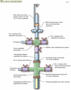
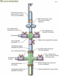
The explosion created a 1.5-m deep and 2-m diameter cone-shaped pit. The wellhead tree exploded and flew away from its original position. The only wellhead remnants left aboveground were the tubing assembly. Fig.1 indicates the severity of the explosion and Fig. 2 shows the location of the remnants.
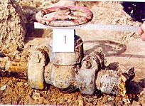
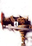
The main body of the tree exploded completely, flying away from the well and cracking. The tubinghead and casing spool valves exploded. Two casing spool valves had broken bodies. One valve was still connected to the injection pump (Fig. 3a), while the other was connected to the damaged assembly (Fig. 3b).
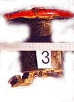
Two tubinghead valves and master valve were destroyed, breaking into pieces and flying far from the wellhead (Figs. 3c, 3d, and 3e).
The casing spool outlet broke crosswise (Fig. 3f), and the 139.7 mm (5.5 in.) casing connected to the outlet broke at the last engaged thread on the pin. The broken pin remained in the casing spool.
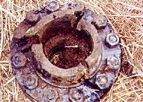
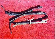
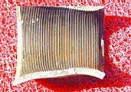
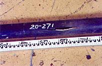
The damage on the tubulars is seen in these photos. The photos on the top show the tubing remnants (Fig. 4a) and the swollen tubing coupling (Fig. 4b). The bottom photos show a remnant of the casing (Fig. 4c) and the crack caused during the hydraulic test (Fig. 4d).
The bottom flange of the tubinghead broke crosswise and cracked in several places. The 73 mm (27/8 in.) tubing connected to the tubinghead broke at the last engaged thread on the pin. The broken pin remained in the tubinghead.
These photos show some of the damage caused by the explosion. Starting on the upper left, the first photo shows the casing valve No. 1 that remains connected to the injection pump (Fig. 3a), casing valve No. 2 (Fig. 3b), and tubing valve No. 3 (Fig. 3c). The bottom photos show tubing valve No. 4 (Fig. 3d), master valve No. 5 (Fig. 3e), and an outlet of the casing spool (Fig. 3f).
null
null
null
null
null
The master valve was left in the open position while the two tubinghead valves and two casinghead valves were found in closed. An inspection of the destroyed equipment indicated the valves attached to the tubinghead were more serious damaged that those connected to the casing spool.
Tubular remnants
The tubing below the wellhead exploded into strips that were found far from the wellhead. The inside, outside, and fractured surfaces of the tubing remnants were black (Fig. 4a). In addition, one broken tubing coupling was flung far from wellhead and had a swollen OD of up to 126-mm (5 in.) compared with the initial OD of 88.9-mm (3.5 in.).
The casing in the ground swelled to 230 mm (9 in.) from an initial 139.7-mm. The casing remnants were larger than the tubing remnants.
Fig. 4b shows one of the casing remnants that is 1,160 mm (45.7 in.) by 180 mm (7 in.). Another casing remnant was 2,300 mm (90.6 in.) by 230 mm (9 in.). Dents caused by the exploding tubing were noted on the inside surface of the casing remnants.
Causes of the accident
The analysis on the remnants indicated that the explosion originated inside the tubing string for the following reasons:
- The severity of damage to the tubing was greater than that of the casing. The casing remnants had swollen to a larger size but the tubing body remnants became small strips. The tubing coupling also swelled and cracked.
- The tubing could not explode first if the internal pressure were the same as in casing. The burst pressure of the tubing is twice as great as that of the casing, so that the pressure during the explosion had to be greater in the tubing than in the casing. The 139.7 mm, J-55 casing has a 6.2 mm (0.24 in.) wall thickness, while the 73 mm, J-55 tubing has a 5.51 mm (0.21 in.) wall thickness.
- The tubing would not have broken into small pieces if the explosion originated in the tubing-casing annulus. If the explosion began in the annulus, the tubing would have collapsed and the casing would have swollen.
- The tubing spool outlets and valves connected with the tubing string showed more damage than the casing spool outlets and valves connected to the casing string.
From the evidence, it appears that the explosion started below ground about 1.5 m below the wellhead tree.
Prior to the cleanout job, the tubing string pressure was about 0.6 MPa (87 psi), so that it could not explode without external forces.
Explosive nature
Mechanical internal pressure and chemical energy can cause the tubing to fail.
With a mechanical failure, tests and studies indicate that during mechanical failure the speed of energy and pressure increases is slow, so that a vessel will deform and crack instead of explode.
The mechanical induced pressure creates only one crack if the vessel material is strong. The crack width also will be small because pressure decreases as the crack grows. Also the 28-MPa maximum pump pressure during the treatment was less than the tubing burst pressure.
Chemical explosions are different because the energy-increases rapidly and there is not enough time for a vessel to deform and slow the buildup of internal pressure. Therefore, the vessel will burst, as previously discussed in the case of this well.
Another observation pointing to a chemical explosion was that all inside, outside, and fracture surfaces of tubing remnants were darkened because of the high-temperature gas created during the explosion. In a mechanical failure the fracture surfaces have a metallic color.
Also twice as much energy is needed to swell a coupling compared to the body of the tubing. A mechanical failure would have created a failure in the body but not the coupling.
Explosive material
Prior to the explosion, the tubing contained oil, gas, water, and the cleanout fluid with 18-20% H2O2.
The key is the H2O2 that is an oxidant with a strong explosive nature. As H2O2 concentration reaches a certain limit, it will release heat and oxygen and cause an explosion.1 Steel as well as its dioxides and salts are good catalysts for the H2O2 decomposition reaction. In the presence of iron as well as its oxides and salts, the decomposition reaction is as follows:
null
H2O2 can decompose rapidly and combine with oil products that easily burn and explode at temperatures greater than 100° C.
H2O2 can react rapidly with oil and gas in the tubing string as the released O2 and heat builds up. The pressure increases quickly as the temperature approaches the ignition point of oil and gas. The explosion occurs as the internal pressure becomes greater than the burst pressure of the tubing.
The damage on the tubulars is seen in these photos. The photos on the top show the tubing remnants (Fig. 4a) and the swollen tubing coupling (Fig. 4b). The bottom photos show a remnant of the casing (Fig. 4c) and the crack caused during the hydraulic test (Fig. 4d).
null
null
null
Test simulation
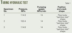
A hydraulic simulation verified the conclusion that the explosion was chemical in nature. Table 1 shows the test results, and Fig. 4d shows the tubing specimen with a crack in the form of a bamboo leaf.
Figs. 5a and 5b show the explosion remnants and the crack in the test tubing.
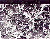
Table 2 and Figs. 5a and 5b illustrated the difference between the remnants of the tubing and casing and the fracture caused by the hydraulic test. The explosion caused brittle cleavage and quasi-cleavage while the test created a dimple form.
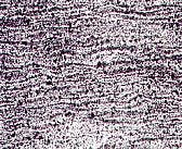
Figs. 5c and 5d compare the metallurgical samples from the explosion and the test. These figures and Table 3 illustrate that the explosion produced decarbonization, deformation, and a recrystalized structure. These conditions were not observed on the test sample during the hydraulic simulation.
The carbon and alloy of the tubing remnants are lower than that of the casing remnants and hydraulic test tubing. The reason is that the tubing pipe body in the explosion experienced high temperature and internal pressure, thereby burning away the carbon and alloy in the steel.
Remnant features
The metallurgy and fracture morphology of the explosion remnants differ from that of the hydraulic test tubing. The pressure to crack the tubing hydraulically was four times greater than the maximum operation pump pressure, so that the possibility of mechanical failure due to the 28-MPa pump pressure during the cleanout can be eliminated.
The explosion remnants of the tubing pipe body have a changed metallurgy from the normal pearlite and ferrite. Seen in the analysis were deformation and a recrystalized structure in most areas of the tubing coupling but little deformation and recrystalization in the casing remnants.
The metallurgy of hydraulic test tubing contains pearlite and ferrite that differs completely from tubing and casing remnants.
The deformation and recrystalization results from some crystals being parallel to certain directions and some crystal faces being parallel to certain faces after deformation of the metal.2 The tubing is more deformed than the casing.
The decarbonization temperature of the metal is about 700-800° C.3 The decarbonized tubing pipe body shows that temperature reached 700-800° C. when the tubing burst.
The morphology of the remnants from the explosion and the hydraulic test differ. The photos above compare the cleavage and quasicleavage in a tubing remnant (Fig. 5a) to the dimple morphology of the tubing in the hydraulic test (Fig. 5b). The bottom photos compare the tubing remnant metallurgy (Fig. 5c) with the metallurgy of the tubing in the hydraulic test (Fig. 5d).
Recrystalization took place in the tubing remnants when the temperature reached the recrystalization temperature before the actual explosion. Mechanical failures cannot reach such a high temperature and energy states. Only a chemical reaction can show the features of both high temperature and energy.
The metal fractures in chemical explosions will be brittle due to high energy applied. Compared to the fracture in hydraulic test tubing, the fractures of the explosion remnants are brittle. This shows the high internal pressure at the moment of explosion. Only chemical explosion can act on the tubing with such high energy.
Acknowledgment
The authors thank Terry Changyi Qi for his review of this article.
References
1. "Encyclopedia of Chinese chemical products," Chemical industry publishing company July 1994
2. Song Yujiu, "Design, choose and forecast of metal material," Xi'an Jiao Tong University, China, October 1998
3. Heat standard application handbook, China National Heat Treatment Standards Institute.
The authors
Lu Shuanlu is a research engineer at Tubular Goods Research Center of China Petroleum Corp. Since 1983, he has worked on aspects of failure analysis, inspection, and supervision of tubular engineering and drillstrings.
Zhao Kefeng is a research engineer at Tubular Goods Research Center of China Petroleum Corp. Since 1982, he has worked on aspects of failure analysis, inspection, and test of tubular engineering, and drillstrings.
