Oil spill risks assessed for offshore arctic pipeline
A detailed analysis has determined that steel pipe-in-pipe designs have less risk of failure than several alternative designs for the proposed Liberty Pipeline to transport oil ashore from a production site in the Alaskan Beaufort Sea.
The study also found that risk was affected by the water depth of the hazard, the failure mode (crack, rupture, pinhole), performance of the monitoring system, third-party activities, and operational failures.
The analysis defined risk as the volume of oil expected to be released over the planned pipeline's 20-year life. Conducted by BMT Fleet Technology Ltd., Kanata, Ont., it used quantitative risk assessment to compare design alternatives. Where historic performance data were not available, engineering models evaluated the probability and consequence of failure.
The risk assessment demonstrated the primary differences of the proposed design alternatives and identified the key factors affecting the oil spill risk.
The investigation considered the risks from ice gouging, strudel scour, permafrost thaw subsidence, operational failures, corrosion, third-party activities, and thermal loads leading to upheaval buckling.
Event probabilities for these hazards were established through development of event trees which combined historic operational failure statistics and those estimated through engineering analysis.
A pipeline leakage consequence model quantified the oil volume released during pipeline failure events such as rupture, through-wall cracking, and pinhole leaks. The model considered secondary containment and the expected performance of leak detection and monitoring systems.
Total estimated spill volumes considered times to leak detection, shutdown, and line evacuation.
Liberty Pipeline project
The Liberty Pipeline would transport oil to onshore Alaska from BP Amoco's Liberty site in 22 ft of water inshore of the Barrier Islands in the Alaskan Beaufort Sea.
The offshore portion of the pipeline is 6.12 miles long.
Four pipeline concept designs were evaluated:1
- Single carrier pipe.
- Carrier pipe inside a steel pipe.
- Carrier pipe inside a high-density polyethylene pipe.
- Single layer composite flexible carrier pipe.
This article will focus on the calculation of failure probabilities and the calculation of spill volumes. More detailed information on the entire risk assessment is provided in References 3 and 4.
- Risk assessment
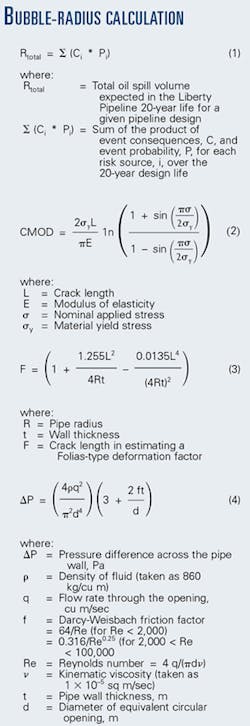
Liberty Pipeline's risk assessment considered the expected amount of oil spilled during the 20-year design operating life of the pipeline. The total risk is shown as Equation 1 (Equations box).
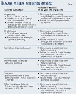
With risk defined, a hazard-identification exercise then defined the hazards of interest. Table 1 outlines these hazards and evaluates their probabilities.
Fig. 1 estimates failure probabilities for those modes of failure not supported by historical industry statistics. These steps include:
- Evaluating the probabilities of occurrence of initiating events.
- Analyzing the pipeline's response to these events.
- Comparing the pipeline's response to established failure criteria.
The ice-gouging hazard is difficult to analyze because there is a wide range of scenarios and little information available to evaluate the ice keel-soil-pipe interaction.
Three general interaction types are possible:5
- Zone 1—The pipeline is above the keel bottom and thus contacts the moving ice keel.
- Zone 2—The pipeline is below the keel bottom and thus is not contacted by the ice. Large soil displacements, however, may occur, producing strains in the pipeline.6
- Zone 3—The pipeline is far below the bottom of the ice keel and is, therefore, safe.
The risks were considered independently for each of these zones. A Zone 1 interaction was assumed to result in pipeline rupture; thus no structural analyses were performed. Oil-spill risk for Zone 1 was evaluated based solely upon the probability of ice-pipe contact and consequence modeling.
In a Zone 2 interaction event, the pipeline route is crossed once by an ice keel, and soil displacements occur that load the pipeline. Investigators reviewed available ice-gouge data to evaluate this event.
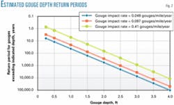
The data set is quite small, which introduced uncertainties, because ice conditions are known to vary year to year. The greatest uncertainty was defining the gouge impact rate (the number of new gouges expected to cross each mile of the pipeline route per year). The analyses suggested that gouge impact rates might vary from about 0.049 to 0.410 gouges/mile/year.
As a result, event probabilities were evaluated for three impact rates spanning the expected range (Fig. 2), recognizing that gouges only occur in water depths greater than 10 ft.
With the ice-gouge event probabilities established, investigators evaluated the pipeline response by estimating the pipe strains in a Zone 2 interaction. In practice, these are governed by the soil property-dependent displacements, ice-related parameters such as the ice keel strength and the ice keel vertical uplift.
Investigators evaluated soil-pipe interaction with displacement-controlled analysis in which the key inputs were the soil displacement field beneath the gouging ice feature, the temperature differential, and the pipeline operating pressure.
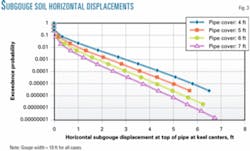
Algorithms based on small-scale centrifuge tests calculated subgouge soil displacements because these represented the only publicly available information.6 Subgouge soil displacement exceedence probabilities (Fig. 3) were calculated for the gouge-depth return periods (Fig. 2), for gouge widths of 18 and 30 ft, which represent worst-case gouge widths for the pipeline.
The maximum pipeline strains and stresses were strongly affected by the gouge width (the loading width) for gouge widths in a certain range.
Investigators used ANSYS Inc.'s large displacement, nonlinear, finite-element modeling to calculate pipe response (strains, stresses) in relation to the subgouge soil displacements that loaded the pipeline. Investigators used analysis of global behavior to determine the structural response of the single-pipe design.
Global behavior
Global pipeline behavior modeling included the effects of internal pressure (1,415 psi) and thermal strains on the pipe elements (ANSYS Pipe 20).7 The pipe elements were supported by axial soil friction spring elements (ANSYS combin 39) that were loaded by the prescribed soil displacements applied at the free ends of the lateral displacement soil spring elements.
The thermal loading due to the difference between the construction (30° F.) and operating temperature (150° F.) induced a compressive load that accentuated lateral deformations, while the pipe internal pressure resulted in an effective stiffening of the pipe section.
The element sizes increased with distance from the center of the model, where the prescribed displacements were applied to the ends of the model.
This model is an engineering approximation of expected pipeline behavior because:
- The potential for buckling and wrinkling that could affect the pipe stiffness was not considered.
- The prescribed displacements might not be realized due to limits on the ice keel strength.
- The analysis only considered pipe displacements in the horizontal plane.
- The effects of pipeline shutdowns or post subgouge event spring back on strain reversals were not considered.
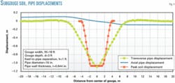
Analyses similar to those shown in Fig. 4, comparing pipeline axial and lateral displacements with the applied soil displacements, were developed for a range of subgouge displacement fields associated with ice gouge event magnitudes.
The analyses indicated that the lateral displacement and curvature of the pipeline (bending moments) was essentially nil outside of a 40 m-wide zone centered on the gouge centerline. This information was used in setting up the local detailed finite-element model to investigate the behavior of pipe-in-pipe construction.
Also, the peak pipe transverse displacement exceeded the soil transverse displacement due to the deformation accentuation from the pipe compressive load. This resulted from temperature change and internal pressure. This exceedence of the soil displacement indicates that the pipe is buckling in its natural mode shape as the soil is displaced.
Local behavior, pipe-in-pipe design
Investigators developed a local finite- element submodel to consider the relative movement (sliding) between the carrier pipe and the outer pipe when considering a cased or pipe-in-pipe design.
These local models demonstrated the ability of the pipe-in-pipe systems to reduce strains on the inner carrier pipe compared to the single-pipe alternative. In the pipe-in-pipe alternative, the inner carrier pipe had significantly lower strains than the outer pipe.
The peak pipeline strains were used to develop a relationship between pipeline maximum strain and ice gouge characteristics.
Failure criteria
Pipeline material failure criteria were needed to examine the limiting strain that would define the onset of failure. Traditional structural or pipeline design has been based on keeping stresses below the elastic limit.
While these are safe design criteria, they are very conservative when predicting the ultimate strength failure or loss of product containment.
Modern pipeline design standards permit small amounts of plasticity, yet they are still considered conservative with regards to pipeline rupture criteria. Because strain limits as high as 5-10% plastic strain could be acceptable, an alternate failure criterion was developed based upon full-scale pipe flexural load trials.
Trials completed for the Northstar Pipeline project by Stress Engineering Services, Houston, in 1998 included full-scale bend tests on welded pipe segments containing machined flaws of the same diameter and grade as the Liberty Pipeline. These tests indicated that 10% strains could be supported without leakage. Based on these test results and others, the following failure criteria were conservatively developed:
First loading cycle of the pipeline, 10% Von Mises strain limit.
Multiple loading events (multiple ice gouge events, in which the pipeline is crossed several times by an ice keel, producing stress reversals), 15% cumulative Von Mises strain.
Industry spill stats
A variety of sources contributed to the development of typical oil spill volume statistics for the Liberty Pipeline design alternatives.
This method of estimating the consequence of a failure event has been applied to operational or maintenance failure modes (oil spilled during maintenance activities). It was noted that engineering judgment had to be applied to ensure that the hazards and failure modes were applicable to an offshore oil pipeline or the particular design alternative being considered.
For example, third-party damage from excavation equipment was not considered for an offshore pipeline.
Oil spill volumes were calculated directly for each hazard, taking into account:
The chain of events that would lead to an oil spill.
The pipeline failure mode that would be expected for each hazard.
The effect of leak detection and monitoring systems.
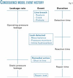
Fig. 5 summarizes the approach taken for calculating oil spill volumes. The model considered line breach, leak detection, and line shut-in and repair.
The type of breach and remedial actions taken were considered in estimating leakage (spill) rate. The type of leak detection system and operator reaction times were considered in estimating the duration of each stage in the oil spill consequence model.
Failure modes, oil flow rates
The first step in modeling these hazard-induced failure consequences was to assign a pipeline failure mode to each failure event. Rupture, leak, and seepage were the three spill-release mechanisms considered.
Rupture is complete separation of the pipeline, allowing oil to spill at a line's design flow rate. Leak is the oil spill rate, for this case based upon flow through a large stable crack-like flaw. Seepage is flow through a pinhole in the pipe.
Table 1 describes the assignment of oil spill mechanisms to each hazard-induced failure mode.
The oil flow rate associated with a rupture, prior to detection, was assumed to be 65,000 b/d, which is the planned oil transmission rate for the line.
The leakage rates through a stable crack or a pinhole are significantly lower.
The largest stable crack that can be supported by the pipeline was estimated with a crack-like flaw failure assessment technique outlined in British Standard PD6493 that considers the interaction of fracture and plastic collapse failure mechanisms.
The critical crack length for a pipeline depends on material properties and pipe geometry. While the nominal Liberty Pipeline pipe material properties (Grade X-52) and geometry are known, the fracture toughness (crack tip opening displacement CTOD, d) of the base metal and weldments were not known.
A sensitivity study evaluated the impact of various CTOD values, which demonstrated that it was reasonable to assume a 250 mm long, through-thickness flaw.
The crack mouth opening displacement (CMOD) must be established in order to calculate the pipe opening area for the critical crack lengths. The amount of pipe wall bulging at the crack due to internal pressure is also calculated for longitudinal flaws. Equation 2 estimates the CMOD.8
The load applied to the crack from the internal pressure produces the bulging deformation. In a fracture mechanics approach, the effect of bulging is accounted for with a Folias factor,
and a similar formulation has been used to estimate the effect of bulging on CMOD.8
Magnifying the plate axial extension CMOD accounts for bulging by considering the pipe radius, wall thickness, and crack length in estimating a Folias-type deformation factor (Equation 3).
Considering Equation 3, and the potential internal pipe pressures, allows estimation of the crack mouth opening displacements for the axial and circumferential cracks for the internal pressure levels of interest.
The crack mouth opening closes with reduced pressure, and at lower pressure, the bulging effect is neglected. Assuming that the crack edges are parabolic arcs transforms the crack mouth opening displacements into opening areas.
The leakage rate through a small opening, such as a crack, may be estimated as an orifice flow problem where the leakage rate is a function of the pressure differential across the pipe wall and the estimated opening area. The leakage rate is related to the pressure difference across the pipe wall (Equation 4).
Equation 4 was solved for the opening areas of interest. As expected, the flow rate increases with the pressure differential and with the opening area.
Leakage rates for pinholes were determined with a similar approach with the size of pinholes being estimated at 1-3 mm diameter based on experience and engineering judgment.
Leak detection, monitoring
The capabilities of the proposed leak detection or monitoring systems assessed the time before remedial actions are taken. It was presumed that the Liberty Pipeline would be fitted with a pressure point analysis/mass balance line pack compensation (PPA/MBLPC) monitoring system.1 2
The parameters assessed included the leak-detection thresholds, the alarm time, and the number of false calls.
Pipeline failure by rupture or flow through a large stable crack would be detectable by the PPA/MBLPC monitoring system, but it would not detect seepage.
Once leakage is detected, the primary response would be to shut in the system. The time between detection and shutting in the pipeline includes the time required to make a decision to take action and the time required to initiate the action.
This includes the time required for the operator to review the alarm and to initiate pump shutdown and line isolation. Industry data and operational experience suggested a 5-min reaction interval as a conservative time estimate to start shutting in a leak, as Liberty would be a short line with the polling rate for the detection systems less than 1 sec.
The PPA system would confirm the initial leak warning within 1 min and initiate shutdown.
After a leak has been detected and confirmed by the operator, line shutdown would be initiated by shutting off pumps and isolating the line. Valve closure would take about 8.5 min. Investigators calculated leakage volumes until the valve is closed by presuming that the pipeline would continue to operate at a rate of 65,000 b/d with an internal pressure of 1,415 psi.
In addition to the oil released during valve closure, another 27 bbl would likely be discharged due to expansion of the oil in the 7.5-mile-long line as the pressure fell to about 0 psi from 1,415 psi.
For pipeline failure by leakage through flaws or cracks, tight cracks would stop leaking once the pressure was reduced sufficiently to close the crack, but the worst case of reducing the pressure to zero was assumed for this project. Once the pipeline flow was stopped and the line shut-in and depressurized, the leakage rate would significantly slow but not stop. Drainage would continue until one or more of the following:
All of the oil capable of being drained from the line is released.
The pipeline opening is repaired.
The oil is evacuated from the line (line is purged).
Because times for the above are difficult to estimate, investigators calculated the volume of spilled oil by conservatively assuming that all oil capable of draining out of the pipeline is released.
Effect of location
Damage location affected the consequence modeling in two ways: It governed the applicable water depth ranges, and it controlled the amount of oil drainage from the line.
Each hazard was considered for a different range of water depths. For example, ice gouging was only a concern in segments of the pipeline at water depths greater than 10 ft because gouges in shallower water are likely to occur at the Liberty site. Ice gouging was only allowed to pose a risk for deeper water. The amount of oil capable of being drained was calculated based on the leak location and the elevation profile of the pipeline.
The calculated oil volumes were limited to the offshore portion of the line, as the valves at the shore crossing and at Liberty Island would presumably be closed.
Furthermore, several high spots would act to trap oil, and the elevation of the oil-water interface was assumed to be at the elevation of the leak. In the shallower regions, the water would sink to the bottom of the pipe, thus displacing most of the oil in the line.
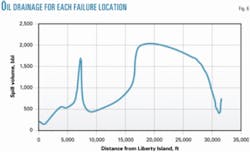
Investigators estimated the potential drainage volume associated with a leak at each location in the pipeline by considering the elevation profile of the pipeline (Fig. 6).
Here are the steps and assumptions used in estimating the oil spill leakage volume:
- The line is at full operation at the instant failure occurs.
- Oil is pumped into the line at the production rate of 65,000 b/d.
- The leak is detected.
- The decision is made to initiate line shut-in, and line shut-in is commenced.
- The flow rate is reduced, as the line is shut-in and depressurized.
- Oil is slowly released after shut-in, and all possible oil is drained from the line.
The oil drainage element of the spill release process constituted the main spill volume (about 70% of the total for each hazard).
Investigators calculated the oil spill risk for each design alternative using Equation 1.
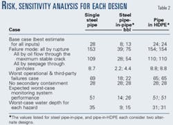
In order to understand the significance of the assumptions made in the risk assessment, a variety of sensitivity studies evaluated the impact of different assumptions. Table 2 shows the oil spill risk estimated for each design alternative, along with the results of the more-significant sensitivity studies.
Study findings
The analyses produced the following conclusions:
- The steel pipe-in-pipe designs had less risk than the others.
- The reduced risk for the steel pipe-in-pipe designs was due primarily to the effects of secondary containment. All designs had the same risk if it was presumed that there was no secondary containment (Table 2).
- The water depth at which the different hazards occur affected the risk, as it controlled the total oil drainage from the line. Consequence modeling showed that drainage caused the majority of the oil loss associated with pipeline failure.
This highlighted the importance of prompt action once a leak has been detected. For example, the study showed the oil spill risk could be reduced substantially by purging the line once a leak had been detected, thereby preventing full drainage.
- The failure mode, as expected, had a very strong influence on the total volume of oil that could lost, with the greatest volumes resulting from a rupture, followed by flow through a stable crack, and finally by seepage through a pinhole.
- The performance of the leak-detection monitoring systems was important for all design alternatives, as the total risk in each case was approximately doubled by a reduction in the monitoring system performance. As expected, the steel pipe-in-pipe design was least sensitive to this assumption owing to the effects of secondary containment.
- Operational failures and third-party activities were the most significant hazards for all designs.
- The total risk was relatively insensitive to parameters such as ice gouging frequency, subgouge soil displacement algorithms, strudel scour generation rates and size, corrosion, occurrence probabilities for thaw subsidence, and upheaval buckling.
Acknowledgments
This project was sponsored by the Minerals Management Service, US Department of Interior. I. Konuk of the Geological Survey of Canada provided assistance through technical guidance and numerical modeling of pipeline structural response.
References
1. Intec Engineering, "Draft Report, Pipeline System Alternatives: Liberty Development Project Conceptual Engineering, Intec Project No. H-0851.02, Project Study PS-19," prepared for BP Exploration (Alaska), 1999.
2. Intec Engineering, "Final Report, Pipeline System Alternatives: Liberty Development Project Conceptual Engineering, Intec Project No. H-0851.02—Project Study PS-19," prepared for BP Exploration (Alaska), 2000.
3. Comfort, G., Dinovitzer, A., and Lazor, R., "Independent Risk Evaluation for the Liberty Pipeline," report submitted by BMT FTL to the US Minerals Management Service, 2000, report posted on the MMS website, www.mms.gov.
4. Comfort, G., Dinovitzer, A., Lazor, R., and Hinnah, D., "Offshore Arctic Pipeline Oil Spill Risk Assessment," International Pipeline Conference, Calgary, Oct. 4-8, 2004.
5. Palmer, A., Konuk, I., Comfort, G., and Been, K., "Ice Gouging and the Safety of Marine Pipelines," OTC Paper 6371, 22nd Offshore Technology Conference, Houston, May 7-10, 1990.
6. Woodworth-Lynas, C., Nixon, D., Phillips, R., and Palmer, A., 1996, "Subgouge Deformations and the Security of Arctic Marine Pipelines," OTC Paper 8222, Offshore Technology Conference, Houston, May 6-9, 1996.
7. Konuk, I, and Fredj, A., "Liberty Pipeline Pipe Soil Interaction Modeling," Geological Survey of Canada, private communication, 2000.
8. Graville, B., and Dinovitzer, A., 1996, "Strain-Based Failure Criteria for Part-Wall Defects in Pipes," ASME International Conference on Pressure Vessel and Piping, Montreal, July 21-26 1996.
9. Folias, E.S., "The Stresses in a Cylindrical Shell Containing an Axial Crack," Int. J. Fracture Mechanics, Vol. 1 (1965), pp. 104-13.
Based on a presentation to the Offshore Mechanics and Arctic Engineering Conference, June 4-8, 2004, Vancouver.
The authors
Aaron Dinovitzer ([email protected]) is vice-president of BMT Fleet Technology Ltd. (FTL), Kanata, Alta. He manages the FTL materials and welding division, where his work centers on the development and application of structural damage tolerance (fitness-for-purpose) analysis techniques in the design and maintenance of structural systems. He holds an MS in civil engineering from the University of Waterloo, with a focus on reliability-based and optimal structural design.
George Comfort ([email protected]) is manager of BMT Fleet Technology Ltd.'s Cold Regions Technology Centre, Kanata, Alta. In his career he has primarily worked on ice and cold regions problems. Comfort holds a BS (1975) in civil engineering from Queens University, Kingston, Ont.
Robert Lazor ([email protected]) is BMT Fleet Technology Ltd.'s manager for western Canada, Edmonton. He has more than 20 years' experience in materials selection, quality assurance procedures, welding metallurgy, engineering assessments, pipeline repair methods, pipeline integrity assessements, and failure investigations. Lazor holds BA and MS degrees in mechanical engineering, with emphasis in materials science, from the University of Waterloo.
Dennis Hinnah ([email protected]) is a petroleum engineer with the US Department of the Interior, Minerals Management Service, in Anchorage. He is responsible for developing regulatory and technical policies and for leading technical reviews of industry proposals for offshore oil and gas exploration and development in the Arctic.
Hinnah has more than 20 years' experience in various engineering positions within the Department of Interior. He has a BS in geological engineering from the University of Missouri-Rolla and has done post-graduate work at several universities.
