Simulation study compares ethane recovery in turboexpander processes
A simulation study of five ethane-recovery processes showed that significantly higher ethane recovery results in turboexpander processes that have a gas-liquid and gas-gas exchanger and use the gas to provide required bottom reboiler duty. The study shows that adding a reflux stream significantly decreases ethane recovery; including a cold liquid exchanger or a second expansion stage yields nearly the same ethane recovery results.
Results show, therefore, that additional complexity in the design of ethane recovery plants is not necessarily useful and may lead to either lower or insignificant additional ethane recovery.
C2+ recovery provides ethane, a valuable petrochemical feedstock, in addition to C3+, which includes LPG, n-butane, i-butane, and natural gasoline.
Using oil absorption to recover NGL is expensive and hard to operate.1 It also has a high fuel requirement to separate the absorbed NGL and remove dissolved methane or ethane from the absorber oil.2
Cascade refrigeration is complex and requires high compression horsepower.2 On the other hand, mixed refrigerants, common in LNG terminals, have been proposed for an NGL-recovery process in which 79% of the propane is recovered; the process was compared to an equivalent typical turboexpander plant (OGJ, Mar. 4, 1985, p. 116).
Turboexpander plants are the most common for NGL recovery, but refrigeration may be more economical if the gas is rich and ethane recovery not required.1 Typically, a dehydration unit using solid desiccant is required to reduce the water content to low concentrations to avoid hydrate formation in the low-temperature section of the NGL-recovery unit.
The turboexpander plant is a popular process for achieving high ethane recovery.3
Our study shows that operators should carefully consider the inclusion of a turboexpander plant; a decrease in recovery or no significant additional ethane recovery can result from a more-complex recovery process.
Process requirements
Our study compared five different turboexpander ethane-recovery processes. All processes maximize ethane recovery, and our comparison includes the optimized processes at the same process requirements.
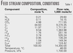
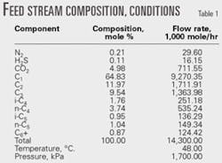
Table 1 shows the feed-gas conditions and composition.
The feed gas consists of three different streams from the three oil-gas separators: low pressure, intermediate pressure, and high pressure gas streams. These streams combine into one (the feed-gas stream) after compression, air-cooling, separation from condensed liquids, and mixing.
In all processes, the feed gas is compressed to 3,100 kPa and then air-cooled. The gas is cooled further to –35° C. by external refrigeration using propane economizer cycle, which requires less compression power than the simple refrigeration cycle.2 The refrigeration duty is 1.304 X 10⁸ kiloJoules/hr.
In all processes, a demethanizer is needed to separate the residue gas from NGL liquid stream. The molar ratio of C1:C2 is 0.02 in all the processes, and the demethanizer top pressure is 1,100 kPa.
Also in all the processes, residue gas is compressed to meet the required pressure for gas transportation.
In the first stage of compression, the expander provides the compressor power. In the second stage, gas is compressed further to meet the required pressure for residue gas transportation. This part of the process does not affect the comparison between the different processes and would unnecessarily complicate the process flow diagrams; therefore, this processing step is not shown in any of the figures.
Figs. 1-5 show the pump that increases NGL pressure because it does not complicate the flowsheets.
Processes
We simulated all the processes using HYSYS process simulator version 3.1; the property package was the Peng-Robinson equation of state. Ethane recovery, our main target, was calculated for each process as the ratio of ethane flow rate in NGL product to the ethane flow rate in the feed gas.
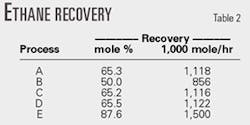
Figs. 1-5 show the different processes; Table 2 summarizes the ethane-recovery results.
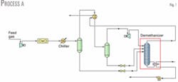
Fig. 1 shows the simplest process (Process A) in which only one gas-gas heat exchanger provides refrigeration recovery. In the first separator, liquid formed by condensation due to cooling feeds the demethanizer after a reduction in pressure to reach the demethanizer pressure.
Gas from the separator enters a gas-gas heat exchanger in which refrigeration is recovered from the overhead product leaving the demethanizer. Overhead gas from the cold separator flows to a turboexpander to lower the temperature to its coldest temperature of –92° C.
Liquid formed in the gas-to gas heat exchanger separates from vapor in the cold separator and flows, after pressure reduction, through a valve to the demethanizer. Varying the temperature of the stream entering the cold separator optimizes ethane recovery. Maximum ethane recovery with Process A was 65.3% and the reboiler duty was 2.655.X.107 kJ/hr.
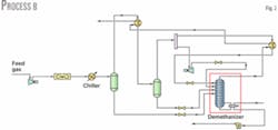
Fig. 2 shows Process B. The process includes a reflux stream added to Process A. Reflux comes from the cold gas stream leaving the cold separator. The stream splits into two streams: one enters the expander and the other (reflux stream) is cooled with the demethanizer overhead stream.
The expander outlet pressure is 2,000 kPa and the stream is split equally. Varying the temperatures of the stream entering the cold separator and of the cooled reflux stream after it exchanges heat with the overhead gas leaving the demethanizer optimizes NGL recovery.
The reflux stream enters the demethanizer at –80.4° C., lower than the temperature of the stream from the expander, which is –78° C. after valve expansion. The reboiler duty is 2.587 X 10⁷ kJ/hr, nearly 2.6% less than Process A.
Process B's ethane recovery, at 50%, is lower than that in Process A. This is consistent with the fact that the reflux stream and the stream from the expander both enter the demethanizer at a higher temperature vs. the single stream leaving the expander in Process A.
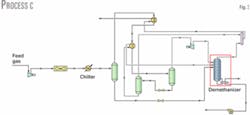
In Process C (Fig. 3), a cold liquid exchanger is added to Process A. Liquid leaving the cold separator is cooled through a valve and then sent to a separator added to separate the vapor formed from the liquid.
The liquid stream cools gas leaving the gas-gas heat exchanger in a gas-liquid exchanger. Vapor leaving the separator does not feed the demethanizer but is mixed with the demethanizer overhead stream.
Temperatures of the two streams leaving the gas-liquid exchanger are varied to maximize ethane recovery. Maximum ethane recovery is 1.116 million mole/hr, which represents a recovery of 65.2%, similar to that obtained for Process A.
Reboiler duty of 2.651 X 10⁷ kJ/hr is slightly lower than that in Process A; therefore there is no real advantage in adding a cold liquid exchanger, at least in this case.
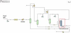
In Process D, expansion occurs in two stages. Because further lowering the demethanizer pressure would require extra compression power for residue-gas transportation, we kept the demethanizer pressure the same for ease of comparison.
Fig. 4 shows the process flow diagram for Process D. After the first stage of expansion, the gas stream further cools in a gas-gas heat exchanger with the overhead gas from the demethanizer. Condensate is then removed in a separator; the overhead gas stream enters the second expansion stage in which it is cooled further while condensation occurs.
Varying the gas temperature after each of the two gas-gas exchangers and the outlet pressure from the first expansion stage allows the maximum ethane recovery. Ethane recovery is 1.122 million mole/hr and the optimum intermediate pressure is 1,955 kPa, which proves that any increase in recovery is not significant compared to Process A.
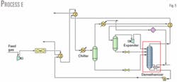
Process E (Fig. 5) has the highest ethane recovery. This process includes some modifications to Process A, mainly to further cool the gas and have more refrigeration recovery. This recovery is enhanced in a heat exchanger after air-cooling.
Feed gas is cooled against the cold NGL bottom product in a gas-liquid exchanger and then with the residue gas in a gas-gas heat exchanger. Propane is then used to cool the gas further.
In Process E, the reboiler duty is provided from heat exchange with the outlet gas stream from the first separator, which further lowers the gas temperature and provides energy needed for the reboiler.
Varying the temperature of residue gas after it cools the feed gas (already precooled by NGL from the demethanizer) and temperature of the gas after cooling from the overhead stream from the demethanizer maximizes ethane recovery.
Ethane recovery is 1.5 million mole/hr, which is 87.6%. Although the reboiler duty is 2.881 X 10⁷ kJ/hr, higher by about 8.5% compared to Process A, a process stream provides this duty, and no extra utility is required.
References
1. Arnold, K., and Stewart, M., Surface Production Operations, Vol. 2; Houston: Gulf Publishing Co., 1999.
2. Manning, F. S., and Thompson, R. E., Oilfield Processing of Petroleum, Vol. 1; Tulsa: PennWell Publishing Co., 1991.
3. McKee, R. L., "Evolution in Design," proceedings of the 56th Annual GPA Convention, Dallas, Mar. 21-23, 1977, pp.123-25.
The authors
R. Chebbi ([email protected]) is a professor of chemical engineering at United Arab Emirates University, Al Ain, UAE. He has also served as an engineer for the Tunisian Ministry of Economy, Shell Tunisie, and Entreprise Tunisienne d'Activités Pétrolières, Tunis, Tunisia. Chebbi has also served as an assistant professor and associate professor at the University of Qatar, Doha, Qatar. He holds an MS (1985) and PhD (1991) in chemical engineering from the Colorado School of Mines, Golden, Colo., and a Diplôme d'Ingénieur (1981) from the Ecole Centrale de Paris.
A.S. Al-Qaydi is a senior student in chemical engineering at United Arab Emirates University, Al Ain, UAE.
A.O. Al-Amery is a senior student in chemical engineering at United Arab Emirates University, Al Ain, UAE
N.S. Al-Zaabi is a senior student in chemical engineering at United Arab Emirates University, Al Ain, UAE
H.A. Al-Mansouri is a senior student in chemical engineering at United Arab Emirates University, Al Ain, UAE
