Case studies demonstrate guidelines for reducing fouling in distillation columns
DISTILLATION— Conclusion
Studying case studies of fouling in refinery and petrochemical plant distillation units reinforces the theories of fouling-resistant designs. Case studies help refine these design practices and standards for fouling services.
Part 1 (OGJ, Aug. 16, 2004, p. 60) presented guidelines for designers to develop—based on their operating experience—practical, serviceable columns for fouling services.
Part 2 will show examples of these design guidelines using case studies of a refinery vacuum tower, ethylene quench oil tower, ethylene quench water tower, ethylene saturators, dilution steam generators, and caustic towers. Examples of butadiene polymer fouling are also covered.
Refinery vacuum towers
Refinery vacuum towers make an excellent case study because they experience many fouling phenomena (Fig. 1). The most problematic part of a vacuum column is the wash bed, which removes entrained bottoms from the distillate products.
Trayed wash sections and packed wash sections both experience problems. Industry has overwhelmingly switched to packing for this service due to its lower pressure drop.
Vacuum towers have low liquid rates in the wash zones. This low liquid rate, coupled with high temperatures, results in long residence times in stagnant sections. This occurs in the packing surface treatment, the interface between packing layers, on packing supports, and in dead portions of random packing.
The average wash-bed run length approaches 5 years. The average life of a wash bed depends on:
- Inlet feed system design. It should reduce entrainment and vapor maldistribution.
- Inlet transfer line design. It should reduce velocity and resultant entrainment.
- Furnace design. This should prevent the high-flux areas that initiate cracking and coking.
- Collector tray design. This can be sloped to reduce residence time.
- Wash bed oil flow rate.
- Amount of vacuum pressure. A deep-cut vacuum results in more velocity gradients, which leads to more entrainment and local low-flow areas.
- Packing and internals.
null
Vacuum tower design options
Baffle trays, particularly shed decks, have provided excellent service in refinery vacuum towers. Shed decks almost never foul because they have no stagnant zones and a low residence time. The drawback is the low stage efficiencies for baffle trays. Baffle trays are still used in some older units.
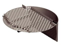
Grid equivalents are also proven for wash zones. They have high capacity and average entrainment removal. Coking and fouling are unusual if the grids are sufficiently wetted. Grids satisfy the design guidelines for packing in fouling services. These guidelines include low pressure drop, smooth surface, and low residence time.
Random packings have been used successfully in vacuum towers. Due to the increased possibility of stagnant liquid pool formation, however, many installations have changed to structured packing or grids.
Structured packings can be used in wash beds if designed correctly. Structured packings in vacuum tower service have greater efficiency at a slightly higher pressure drop compared to grids. Structured packings also have rougher surfaces and a longer residence time.
If the packing dries out due to a wash-bed liquid design that does not use optimized liquid distributors, the packing can foul quickly. This causes high pressure drops, poor product quality, and reduced capacity.
Current designs include a mixed bed of grid and structured packing, which combines fouling resistance in the lower sections and high separation efficiency in the upper sections. Computerized fluid dynamics studies help optimize inlet vapor flow.
Vacuum tower case studies
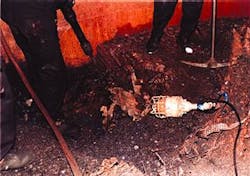
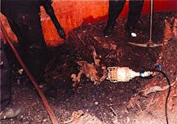
An Asian refiner had trouble maintaining wash oil rates due to plugging spray nozzles; this caused severe fouling (Fig. 1). This tower's run length was less than 1 year. The refiner replaced spray nozzles with a trough liquid distributor; since then there has been no sign of fouling.
The same refinery had a second problem with naphthenic acid attacking the internals. The tower was revamped with improved metallurgy for the internals.
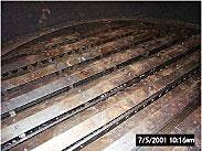
Another Asian refiner's wash bed was converted from random packing to grid packing (Fig. 2) in 1995. This tower is still in service.
The lessons learned are:
- Grid equivalents can perform better than structured packing in lower-section wash beds, but with lower efficiency.
- Wash bed rates are difficult to simulate correctly and must be specified carefully to ensure a long bed life with reduced fouling.
Ethylene quench oil towers
Ethylene quench oil towers can encounter several different fouling phenomena.
The distillation equipment selection process must consider all of the fouling scenarios. The average ethylene unit run length is nearly 6 years.
Quench oil towers experience the formation of coke and fines that deposit on tower internals. The tower internals' design, especially regarding velocities and residence time, must reduce the formation and accumulation of coke and fines.
null
An additional design criterion for ethylene quench oil towers is naphthalene concentrations. In towers processing heavy naphthas, the naphthalene concentration can cycle up. The naphthalene is too heavy to exit the tower overhead and it can recycle back into the tower from the fuel oil stripper, which causes tower flooding.
Quench oil tower design options
Baffle trays, particularly shed decks, are effective for ethylene quench oil towers.
null
A small negative of random packing is horizontal areas where liquid can pool. Fouling can begin to propagate from these areas.
One important point to remember is associated with the commissioning of quench oil towers. Normal guidelines are to circulate No. 2 diesel oil in the system. If the furnaces are on steam standby to the quench oil towers, however, the steam can strip light ends out of the circulation loops, which increases the viscosity of the circulation liquid.
If the viscosity increases to above the pour point, flow from the tower can cease, and it takes several days to clear the fouled lines. Vaporization of volatile components is a concern in ethylene quench oil towers.
The naphthalene concentration can also cause high liquid loads in the quench oil tower's bottom. Naphthalene is too light to exit with the fuel oil in the bottoms stream and too heavy to exit the tower overhead.
Ethylene quench water towers
Ethylene quench water towers in naphtha crackers that have quench oil towers can be relatively trouble-free because the oil tower removes coke fines and heavy hydrocarbons.
Quench water towers for ethane crackers are different. There can be many problems in light-gas crackers including coke fines, pyrolysis tar, and emulsions.
As with the previous examples, baffle trays, particularly shed decks, have provided effective service for ethylene quench water towers. Ripple trays are also effective for quench water towers, as one Asian producer discovered—they have operated for 10 years with no fouling.
Quench water case studies
A US gas cracker commissioned a quench water tower with a combination of spray nozzles and random packing with pan distributors. The random packing was replaced in 1999 and 2000 due to high pressure drop and a loss of capacity. By February 2001 the tower was again experiencing high pressure drop and heat-transfer losses.
In July 2001, the tower was converted to v-notch liquid distributors and grid packing. The tower, after operating for 21/2 years, is still running with a higher capacity, lower pressure drop, and improved heat-transfer capacity than when it was first commissioned.
Another US gas cracker quench water tower was originally designed with random packing in the top bed and structured packing in the bottom bed. The tower was upset during start-up and the packed bed collapsed. The operator then hot-tapped the tower and inserted spray nozzles around the tower's top.
With the ring of hot taps and spray nozzles installed, the tower could run at full rates; however, the tower's top temperature of 115-120° F. was higher than design. The column's bottom temperature was 140-160° F.
In 1995, the tower was revamped with random packing in the top and a draw pan for spray circulation in the bottom. The draw pan was upset during start-up. A later inspection found that the hold-down clamps were improperly installed and bolts were missing. The ring of spray nozzles was reinstalled and the column restarted.
In 2000, the circulation rate suddenly lowered, as if a line had become plugged. The tower was shut down; inspectors found a loose vapor riser hat from the draw pan in the circulation draw. The vapor riser hats were then welded in place.
In September 2003, the tower was converted to v-notch liquid distributors and grid packing. The tower is now performing with a lower pressure drop and improved heat-transfer capacity.
The lessons learned from these two case histories are:
- Inspection of installed tower internals is an important part of a successful column revamp. This is especially true for columns that process hydrocarbons and water. The volumetric expansion of water vaporization is 1,100:1. Any potential for water to vaporize will greatly increase the volume of vapor flow. Combined with improperly installed equipment, this volume increase can cause severe problems.
- Random packing and pan distributors should have limited use in fouling services, especially quench towers.
- A small stream of pyrolysis gas to a quench water tower greatly improves operations.
Ethylene saturators, dilution steam generators
Saturator and dilution steam generator (DSG) tower designs are often problematic. Many technology suppliers provide multiple or small dual units for when the large tower is being refurbished.
Typical problems include:
- Corrosion due to high pH.
- Erosion due to coke particles.
- Fouling due to polystyrene and pyrolysis tars.
- Emulsions due to hydrocarbon carryover from quench water towers and hydrocarbon removal systems, which can be a stripper tower or dispersed oil extraction (DOX) unit.
Environmentally, this is an important system that has two functions. The first is water conservation; the saturator and DSGs recycle water for the cracking furnace, thus reducing the total amount of wastewater generated. A saturator or DSG also reduces hydrocarbon losses to the wastewater treatment system, especially phenols. Hydrocarbons are stripped from the tower bottoms that are sent to the wastewater treatment facility.
Typical DSG, saturator system design
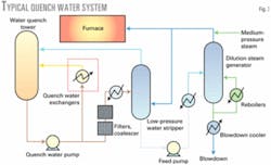
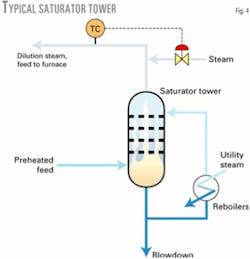
Fig. 3 shows a typical quench system. Fig. 4 shows the design of a typical saturator tower.
Effluent from a pyrolysis furnace feeds a quench oil tower and then a quench water tower for cooling. The effluent is a full-range mixture of hydrocarbons and water.
Water for the dilution steam system is withdrawn from the circulating quench water loop of the quench water tower. It is then treated in filters and coalescers to remove most of the entrained hydrocarbons and coke fines.
The filters and coalescers can be an elaborate system using anthracite and multiple coalescers, sometimes called a DOX unit. Some systems have a low-pressure water stripper that uses steam to strip out the volatile hydrocarbons from the stream that feeds the quench water tower.
The partially stripped or extracted water is introduced into the DSG or saturator tower. The water feed for both systems is typically introduced on the top tray. The hydrocarbon vapor feed stream in saturators is typically introduced at the tower's bottom.
The counter flow of rising vapor generated from the reboilers and the hydrocarbons present allows the stream to leave saturated.
Steam is added to raise the dilution steam temperature to slightly above superheat. This prevents condensation along the dilution steam piping from the tower to the pyrolysis furnace.
The saturator system can also use knockout pots to remove any condensing water. Additionally, a second pass through the furnace can superheat the saturated stream.
Steam is also used in the DSG or saturator reboiler for heat. Blowdowns from furnace steam drums and boilers can also feed the DSG or saturator tower.
Dual-flow trays or other nonfouling distillation equipment, typical for this service, provide fouling resistance. Styrene polymers have been known to foul the top of DSG towers. Heavy compounds leave the dilution steam system in the tower blowdown stream and are sent to the wastewater treatment system.
DSG, saturator design options
Baffle trays, particularly shed decks, have worked well in saturator towers.
Grids fit the design guidelines for packings in fouling service, including low pressure drop, smooth surface, and low residence time.
Baffle trays can be used in DSG tower designs and they might be the preferred option. One Asian producer has successfully used ripple trays; the one drawback is emulsion problems that are related to pH control.
Several producers removed the distillation devices and have only a spray tower. This option is the most operationally reliable but may not be the best solution environmentally.
null
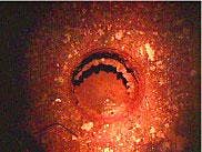
An ethylene plant depropanizer experienced high levels of butadiene polymer fouling (Fig. 7).
null
DSG, saturator case studies
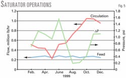
A saturator tower in a US cracking plant was commissioned with a combination of spray nozzles and random packing with pan distributors. The random packing was replaced in 1999 and 2000 due to high pressure drop and a loss of capacity, which occurred only a few months after the packing was replaced.
Fig. 5 shows the tower's operations in 1999.
The pan distributor was replaced with a v-notch distributor without parting boxes to redistribute the flow (Fig. 6). Because this tower is mainly for heat exchange and not mass transfer, the operator did not install the parting boxes, which reduced the potential for fouling.
During furnace commissioning in an Asian ethylene plant, sulfur was added to reduce the catalytic coking of the metal tubes. The sulfur reduced the quench water's pH and it formed an emulsion. A water-styrene emulsion can be difficult to break because both molecules are polar.
The emulsion carried through to the DSG and formed a styrene polymer due to the higher temperature in the DSG tower. Mechanical cleaning was required.
Ethylene unit caustic towers
Ethylene caustic towers have many fouling phenomena: polymerization, sedimentation, precipitation, crystallization, chemical reactions, and corrosion. Caustic towers qualify as a complex fouling system because more than two fouling phenomena occur at the same time and are mutually reinforcing.
A certain amount of polymer formation in a caustic tower is expected in most systems. Caustic tower polymer fouling is a function of acetaldehyde concentration and aldol condensation reactions.
The caustic can polymerize the acetaldehydes to first form a yellow oil polymer and then a red oil polymer by aldol condensation reactions. These polymers can then lead to emulsions.
Caustic tower sedimentation results in salt by-product deposits on the trays' underside. This by-product eventually leads to high pressure drop that results in reduced rates and higher energy consumption in the cracked gas compressor. Some producers use a small continuous pyrolysis gas wash, followed by a larger pyrolysis gas wash when the pressure drop increases.
Caustic tower design options
Caustic towers can use standard sieve deck trays. The advantage of sieve decks is that the processes' chemical reaction rate can be maintained over time.
The negatives are a higher pressure drop compared to packing.
Caustic towers with deck trays have had run lengths exceeding 5 years. Caustic towers have also successfully used random packing.
A small disadvantage of random packing and grid equivalents is the horizontal area where fouling can begin.
Run lengths with random packing have also exceeded 5 years.
The lessons learned in caustic tower designs are:
- Random packing and pan distributors have limited success in fouling services.
- A small injection of pyrolysis gas to a caustic tower greatly improves operation.
- Revamps must carefully consider internal overflows; high pressure drops can result from undersized internal overflows.
Ethylene unit butadiene fouling
An ethylene unit can experience butadiene polymer fouling (Fig. 7) in the de-ethanizer, depropanizer (Fig. 8), and debutanizer columns.
Polybutadiene is sometimes called popcorn polymer because it is pyrophoric and makes a popping sound when exposed to air.
null
null
Polymer formation is temperature dependent and temperatures should be kept below 200º F. to avoid polymer formation.
Standard sieve deck trays can be used in butadiene polymer tower designs. Many producers have successfully used standard sieve deck trays with run lengths exceeding 5 years.
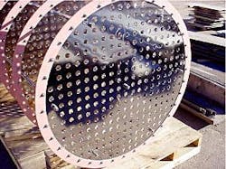
Electropolished trays (Fig. 9) help prevent the popcorn from sticking to trays.
With the short residence times of high-capacity trays (Fig. 10), and the elimination of dead zones on the tray using flow directors and flow promoters, polymer production can be reduced in the tower bottoms where higher temperatures are necessary for proper column operations.
