Advanced dehydrator design recovers gas, reduces emissions
Performance testing of an advanced glycol dehydrator design showed that the unit, compared with a conventional dehydration technology, saved the equivalent of more than 35 million standard cu ft/year of natural gas valued at more than $173,000. It also lowered hazardous air pollutant (HAP) and volatile organic compound (VOC) emissions.
During this test, the new unit produced by Engineered Concepts LLC, Farmington, NM, also reduced CO2 emissions by nearly 3,000 tons/year.
A 1996 study of CH4 emissions from the natural gas industry, conducted by the US Environmental Protection Agency and the Gas Research Institute, estimated that active glycol dehydrators in the US collectively emitted about 18.6 billion standard cu ft/year of CH4.1
These units also reportedly produced 85% and 81% of the production sector's HAP and VOC emissions, respectively.2 3 These considerations make dehydrators ideal candidates for both gas savings and emission reductions.
Testing of the Quantum Leap natural gas dehydration technology (QLT) occurred at the Kerr-McGee Corp. gathering station in Brighton, Colo., in April 2003.
EPA's Office of Research and Development, under its Environmental Technology Verification program, conducted the study. The program operates six centers that focus on testing technologies designed to mitigate a broad range of environmental problems.
This test was conducted by the Greenhouse Gas Technology Center that is comanaged with EPA and operated by Southern Research Institute, Research Triangle Park, NC.
Technology description
The QLT can be configured as a retrofit to, or a replacement of, existing conventional dehydrators.
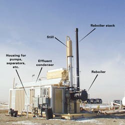
Fig. 1 shows a schematic of the technology as installed at the Kerr-McGee plant and Fig. 2 shows the installed system.
In conventional dehydrators, wet natural gas enters a two-phase separator that divides liquid hydrocarbons from the gas stream. Liquid products feed a condensate storage tank for sale and wet gas flows to an absorber.
Lean, dry triethylene glycol (TEG) directly contacts the wet gas and absorbs water vapor, methane, HAPs including benzene, toluene, ethylbenzene, and xylene (BTEX), n-hexane, and VOCs.
Dry natural gas exits the absorber as pipeline-quality gas ready for sale. The rich, wet glycol exiting the absorber feeds a regeneration reboiler that removes the absorbed constituents resulting in a lean glycol mixture suitable for reuse in the absorber.
The regeneration process is typically the primary source of emissions from a dehydrator. The process contains a process pump, reboiler still, and a variety of heat exchangers.
The process pump moves glycol through the system and is either electrical or, most commonly, a gas-assisted Kimray pump.
High-pressure natural gas powers the Kimray pumps; spent pump gas is usually dumped into the rich glycol stream, flashed off in the regenerator, and vented through the still column. Units with a glycol flash tank upstream of the reboiler can recapture some of the spent gas for reboiler fuel.
The reboiler strips absorbed water, HAPs, VOCs, and CH4 out of the glycol and into the still column. Regenerated lean glycol exits the reboiler, is cooled via cross exchange with returning rich glycol, and enters a surge tank. From there, it is pumped to a glycol-gas heat exchanger and back to the absorber.
This heat exchanger controls the lean glycol temperature to the absorber. High glycol temperatures relative to the gas temperature reduce TEG's moisture-absorption capability. Conversely, temperatures that are too low promote glycol loss due to foaming and increase the glycol's hydrocarbon uptake and potential still-vent emissions.
The still column vent emits stripped water, methane, HAPs, and VOCs to the atmosphere unless a combustion or condensation device controls the stream. Combustion devices include flares or, in the case of the Kerr-McGee site, thermal oxidizers. Condensers include water-knockout systems and other separation systems that produce saleable condensate products.
The QLT system contains these component modifications and additions (Fig. 1): electric glycol circulation pump, eductor, still column effluent condenser, glycol cooler, three-phase vacuum separator, three-phase emissions separator, electric process pump, and two high-efficiency glycol filters.
Circulation of glycol via the circulating pump (A) through the eductor (B) creates a vacuum. This vacuum is controlled at about 4-in. water column (in. WC) and pulls the still column overhead vapors through the still column effluent condenser (C).
The circulation pump provides more glycol than is needed for the eductor; excess glycol cools the effluent condenser. A fan-driven air cooler (D) rejects the heat accumulated in glycol circulated through the effluent condenser.
Still column overhead vapors condense under a vacuum at about 120-130° F. The vacuum separator (E) separates the resulting liquid hydrocarbon-water mixture.
Water is disposed of and hydrocarbon liquids are sent to storage. Because the hydrocarbons are collected under a vacuum, they are stable and no vapor losses or weathering occur.
The vacuum pulls all noncondensable vapors to the eductor where they are compressed to about 30 psig. The eductor outlet stream—a mixture of glycol from the circulation pump and noncondensed vapors from the vacuum separator—feeds the emissions separator (F) where the glycol and vapors are separated.
Vapors are sent to the reboiler fuel system. An electric-powered process pump (G) and high-efficiency filters (H) complete the process.
null
Test setup, equipment modification
The Kerr-McGee gathering facility, 14 miles northwest of Brighton, Colo., processes about 26 MMscfd of natural gas in the dehydrator. The facility installed the new technology because excess moisture in the still vent caused persistent problems with thermal oxidizers.
Table 1 summarizes the test site's key design and operating parameters.
After the new system was installed, operators discovered that the burner and reboiler were operating at an inconsistent temperature. The reboiler was equipped with an electronic thermostat that responded rapidly to small changes in temperature with large increases or decreases in output to the control valve. This resulted in wide temperature swings with alternating periods of heavy firing, which required makeup gas, and corresponding off cycles during which the recovered fuel gas pressure would increase to a point that the eductor was unable to pull an adequate vacuum.
A pressure-relief valve and fuel accumulator were installed to prevent this pressure buildup and to enable proper burner control.
Pressure relief valve
A pressure-relief valve (PRV) was installed in the vacuum separator. It would open to atmosphere when the recovered fuel gas pressure reached 30 psig and close when the pressure was less than 30 psig.
The PRV is a safety device. The system uses this feature only during initial system start-up; the vent remains closed during normal operations.
Fuel accumulator vessel
A 430-gal accumulator vessel was installed to dampen the effects of large swings in reboiler temperature.
The accumulator vessel increased the fuel gas system's reserve volume during high-recovery periods. This allowed the burner to fire with small amounts of makeup fuel during high-firing cycles and provided a pressure cushion to accumulate fuel during low-firing periods.
A pressure-activated valve would open to the atmosphere if the gas pressure in the vessel exceeded 28 psig. This could produce air emissions, but this PRV is a safety device that would actuate during abnormal conditions only. It remained closed during the tests.
Gas processed in the dehydrator had an unusually high btu content. Consequently, the process occasionally recovered more high-btu vapors than it could consume during normal operations. This resulted in a higher fuel pressure and subsequent problems in maintaining an adequate vacuum.
The accumulator helped dampen the system response; but as an added measure, Kerr-McGee installed a water-injection system.
Water-injection system
A compressed-air-driven pump was installed to inject some of the vacuum separator's recovered waste water back into the reboiler. This would increase the reboiler load when necessary, which enabled the burner to demand more fuel.
The fuel-gas pressure and effluent condenser temperature control this pump. The effluent condenser temperature is a key control point because hot vapors cause inefficient hydrocarbon condensation.
The pump operates when the fuel-gas pressure is 20 psig or more and the overhead temperature is 120° F. or less; otherwise, the pump automatically shuts down. The water pump was designed with a reserve capacity sufficient to handle all reasonably expected gas compositions at the test facility.
Performance verification
We verified the operational performance for sales-gas moisture and production rate, glycol circulation rate, and makeup natural-gas fuel flow rate. We also verified the environmental performance of reboiler-stack emission rates and HAP destruction efficiency.
Sales gas
Kerr-McGee continuously monitors sales-gas moisture using a GE Panametrics meter with a moisture measurement range of 0-20 lb H2O/MMscf, a lower detection limit of 0.2 lb H2O/ MMscf, and a rated accuracy of ±5% of reading.
Panametrics calibrated the meter before installation. We used the 1-min average moisture data.
Kerr-McGee uses an Emerson MVS205 multivariable-sensor orifice meter to document sales-gas production. The sales-gas meter contains a 4-in. orifice plate and is temperature and pressure compensated to 60° F. and 14.7 psia (gas industry standard conditions).
The meter's operating range is 0-2 million standard cu ft/hr with a rated accuracy of ± 1% of reading. Site personnel calibrated the flowmeter before testing. We used the meter's 1-min averages.
Glycol circulation
A Controlotron Corp. 1010EP1 ultrasonic meter measured the glycol circulation rate. The meter is a digitally integrated flowmetering system that consists of a portable computer and ultrasonic fluid flow transmitters.
The meter determines fluid velocity by measuring ultrasonic pulse transit times between the transducers. A precision-mounting jig secures the transducers to the pipe at a known distance.
The operator enters the fluid composition (100% TEG for this test), pipe diameter, material, wall thickness, and expected sonic velocity into the meter's computer.
The flowmeter determines sonic velocity based on the known distance between the transducers for zero-flow conditions with the pipe full of fluid. It multiplies fluid velocity by the internal pipe area, and reports 1-min average volumetric flow rates.
The flowmeter's overall rated accuracy is ±1.0% of reading and can be used on 0.25-360 in. diameter pipes with fluid flow rates of 0-60 fps.
Makeup natural gas
The new reboiler burner can accept up to 166 scfh of makeup natural gas as supplemental fuel.
A Halliburton Co. MC-II EXP turbine meter installed on the 1-in. ID gas line upstream of the reboiler measured makeup gas flow. The meter includes an integral-signal display and transmitter with a linear flow range sufficient to measure gas flows if the reboiler operates on makeup gas only (0-600 scfh).
The manufacturer used a piston-type volume prover to calibrate the meter. It is temperature and pressure-compensated, and provided a mass flow output accurate to 1% at standard conditions. We used the 1-min average data from this meter.
Reboiler stack emissions
Cubix Corp., an independent stack testing contractor in Austin, performed reboiler stack emissions testing to determine concentrations and emission rates for: CO, total hydrocarbons, greenhouse gases (CO2, NOx, and CH4), BTEX, and total HAPs, which are BTEX plus n-hexane.
Cubix conducted three 90-min (nominal duration) test runs for each parameter while the system was operating at normal conditions. Emission rates reported in ppm (vol) dry (ppmvd) are correlated with the stack volumetric flow rates in dry standard cu ft/min to yield lb/hr emission rates for NOx, CO, CH4, VOC, hexane, BTEX, and HAPs.
VOC emissions are all organic compounds minus methane and ethane emissions according to Colorado Department of Public Health and Environment regulations.
All the test procedures are documented Title 40 CFR 60 Appendix A reference methods.
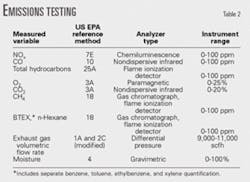
Table 2 summarizes reference methods performed for emissions testing supporting this verification.
HAP destruction efficiency
Destruction efficiency is the net HAPs entering the system from the glycol minus those leaving the system in emissions sources divided by the net HAPs entering the system.
Testers determined the HAPs inputs via the Atmospheric Rich-Lean Method for Determining Glycol Dehydrator Emissions.4
HAP emission sources at this site include: fugitive leaks, reboiler burner exhaust, waste water, and PRVs. We determined that fugitive leaks are negligible because the fabricator certified the system to be leaktight. The burner stack may emit unburned HAPs to the atmosphere; HAPs dissolved in waste water can release during disposal.
Consistent with 40 CFR Part 63,5 HAPs dissolved in the condensate stream are considered to be "controlled" or "sequestered" and not emissions.
We conducted performance testing in two stages: operational testing occurred over 7 days both to obtain reportable flow rate data and to ensure that the plant was operating normally; environmental testing occurred on the following day in three test runs of 70-85 min each.
Test results
Table 3 shows the operational results. Makeup natural gas flow rates are particularly interesting.
We expected the new reboiler to use up to 166 scfh of makeup gas to supplement its fuel supply, but the overall average flow rate was 3.85 scfh. This showed that the unit could use high-btu, wet hydrocarbon vapors as a primary fuel.
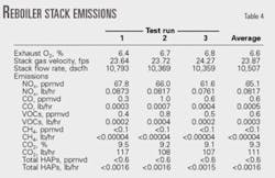
Table 4 shows the reboiler stack emissions results for the three test runs. A continuously extracted stack-gas sample periodically injected into a gas chromatograph provided the material for organic (CH4, HAPs) concentration determinations.
Test personnel performed six injections, each about 15 min apart, during each test run.
The analyst determined that each HAP constituent was consistently below the instrument's detection limit of <0.1 ppmvd. This equates to an average emission rate of <0.0016 lb/hr, which is well below the site's permit requirement.
All CH4 results were also below the gas chromatograph, flame ionization detector's detection limit of <0.1 ppmvd.
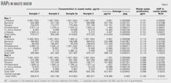
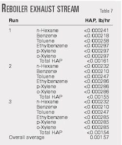
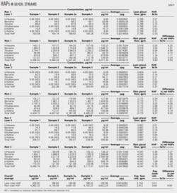
Table 5 summarizes HAP destruction efficiency for each test run and the overall average. The calculation method for total HAP destruction efficiency to sum HAPs in the waste water (Table 6) and reboiler exhaust (Table 7) and divide by HAPs inputs from glycol streams (Table 8).
The operational performance data showed that:
- The moisture content of dry natural gas was well below the 7 lb H2O/ MMscf limit that the operator required throughout the monitoring period. Actual daily averages were 0.89-1.28 lb H2O/MMscf.
- Average sales-gas flow rates were 26.8-29.3 MMscfd.
- The system burned all noncondensable hydrocarbon vapors without venting them to the atmosphere and used little or no makeup gas. Average flow rates of makeup natural gas were 0.63-16.32 scfh with an overall average of 3.85 scfh.
- Daily average glycol circulation rates were 3.0-3.77 gpm.
The environmental testing proved that:
- Overall average emission rates for NOx, CO, CO2, and VOCs from the reboiler stack were 0.0817, 0.0005, 111, and 0.0003 lb/hr, respectively.
- HAP and CH4 concentrations in the reboiler stack were undetectable. Maximum HAPs leaving the system in the reboiler exhaust and waste water were 0.0016 and 0.022 lb/hr, respectively.
- HAP destruction efficiency was greater than 99.74% ± 0.01%.
- PRVs did not operate at any time during the entire test. No releases are anticipated during normal operations; therefore, no expected emissions were assigned to PRV operations.
- Average waste water and condensate-production rates were 6.36 and 2.88 gph, respectively.
Cost savings, emission reductions
The four main sources of cost savings for the new dehydrator result from replacing the Kimray pump, eliminating gas stripping, reducing still column overhead emissions, and lowering thermal oxidizer fuel use.
Kimray pump
An electric pump in the QLT replaced the Kimray pump, which is pressurized with natural gas in typical dehydrators.
The Kimray pump developed a pressure load of 1,070 psig, which worked against the absorber and the glycol flash separator. Kimray literature indicates that, at this pressure, the pump consumes 5.95 scf/gal of glycol pumped or a total of 34,200 scfd based on a 4 gpm glycol circulation rate.
The reboiler in the original configuration consumed some of this gas. It burned about 520,000 btu/hr assuming a 50% efficiency.
The approximate net heating value of gas from the glycol-gas separator was about 1,160 btu/scf according to a process model. This is higher than the plant fuel gas value of 1,107 btu/scf because the gas contained some of the heavier components absorbed by the glycol.
The reboiler therefore consumed 448 scfh and the rest was vented to the thermal oxidizer. Total gas no longer wasted is 34,300 – 448(24) = 23,500 scfd. At 1,160 btu/scf this equals 1.14 MMbtu/hr.
Gas stripping
Because a condensing water exhauster was incorporated into the new design, the gas stripping system (sparger) was no longer needed. The minimum design consumption rate using a sparger was 4 scf of gas/gal of glycol circulated; we assumed that consumption rate for these tests.
At this rate, the sparger used 23,040 scfd of 1,107 btu/scf gas or 1.06 MMbtu/hr. All of this gas was routed to the thermal oxidizer.
Still column overhead emissions
During testing, the new dehydrator recovered 2.88 gph of condensate consisting mostly of HAPs valued at about 0.13 MMbtu/gal, or 0.375 MMbtu/hr. All these condensates previously went to the thermal oxidizer.
Additionally, the still column overhead emissions provided all the process fuel for the new system. The Kimray pump calculation already accounts for this fuel because that is where the old dehydrator obtained it; therefore, 0.52 MMbtu must be added back into the still column calculation.
Total still column overhead emissions no longer wasted is 0.375 + 0.520 = 0.895 MMbtu/hr.
Thermal oxidizer fuel
We did not meter the fuel flow to the thermal oxidizer on the tested unit; however, a parallel dehydrator similarly equipped with a thermal oxidizer that processed the identical gas stream was metered. That dehydrator circulated 6 gpm of glycol. We assumed that the hydrocarbon pickup is similar and that the thermal oxidizer duty is directly proportional.
Fuel consumption in the metered thermal oxidizer, according to Kerr-McGee, is 34,700 scfd of 1,107 btu/scf gas. Fuel for the thermal oxidizer that the new system replaced was therefore (34.7/6) 4 = 23,100 scfd or 1.067 MMbtu/hr.
The total previously wasted gas in the pumps, gas stripping, still column overheads, and thermal oxidizer fuel is 1.14 + 1.06 + 0.895 + 1.07 = 4.16 MMbtu/hr.
At a value of $5.00/MMbtu, the gas saved is worth more than $182,000/ year.
Electric utility costs
The new process required 11.9 kw of electricity to drive the motors for the process pump, circulation pump, and glycol cooler. The conventional dehydrator required 0.8 kw of electricity to power the blower on the thermal oxidizer.
At $0.09/kw-hr, the additional electric consumption of the new process was about $8,800/year.
Payback
Overall savings attributable to the QLT process is about $173,000/year. The process cost about $300,000 but replaced equipment valued at about $225,000. The payback on the incremental difference in capital cost is therefore less than 6 months.
CO2 emissions
The new reboiler consumes about 0.520 MMbtu/hr of a high btu, mixed-hydrocarbon stream and produces 111 lb/hr of CO2. If the thermal oxidizer on the old dehydrator consumed 4.16 MMbtu/hr of a similar mixture of high-btu hydrocarbon fuels, it would proportionally produce about 888 lb/hr CO2.
About 60% of the vapors burned in the thermal oxidizer, however, were methane from gas used by the Kimray pump, gas stripping, and fuel for the thermal oxidizer.
CO2 emissions from the methane portion of the incinerated gas are less than that for higher-btu gas components. Less CO2 emissions to account for the methane yields a value of about 680 lb/hr, or a reduction of about 2,980 tonnes/year.
References
1. "Methane Emissions from the Natural Gas Industry," Vol. 2, technical report EPA-600/R-96-080b, US Environmental Protection Agency, National Risk Management Research Laboratory, Research Triangle Park, NC, 1996.
2. "National Emissions Standards for Hazardous Air Pollutants for Source Categories: Oil and Natural Gas Production and Natural Gas Transmission and Storage—Background Information for Proposed Standards," EPA-453/R-94-079a, US Environmental Protection Agency, Office of Air Quality Planning and Standards, Research Triangle Park, NC, 1997.
3. "Preliminary Assessment of Air Toxic Emissions in the Natural Gas Industry, Phase I," topical report GRI-94/0268, Gas Research Institute, Chicago, 1994.
4. "Atmospheric Rich/Lean (ARL) Method for Determining Glycol Dehydrator Emissions," Gas Research Institute, Chicago, 1995.
5. "National Emission Standards for Hazardous Air Pollutants for Source Categories, Subpart HH—National Emission Standards for Hazardous Air Pollutants from Oil and Natural Gas Production Facilities," 40 CFR 63, US Environmental Protection Agency, Washington DC, June 17, 1999.
The authors
David A. Kirchgessner ([email protected]) has been a senior research scientist for the US Environmental Protection Agency's Officer of Research and Development in Research Triangle Park, NC, for 28 years. The last 11 years have been spent on research directed toward the quantification and mitigation of greenhouse gases from the fossil fuel industries. Kirchgessner received a bachelor's in economics and a master's in geology from the University of Buffalo. He also holds a PhD in geology from the University of North Carolina and a master's in public health administration. He is a registered professional geologist in North Carolina.
Robert G. Richards (bob- [email protected]) is a senior engineer for Southern Research Institute's Greenhouse Gas Technology Center in Research Triangle Park, NC. He has more than 11 years' experience in environmental engineering, 4 years' experience in manufacturing engineering, and 7 years' experience in heavy equipment mechanics. Richards designs and manages test campaigns, commissions a wide variety of field and in-house equipment, drafts associated documentation, and is directly responsible for conceiving and implementing testing, data acquisition, and analysis procedures. He holds a BS in industrial technology (welding engineering) from Utah State University, a BS in Art (ceramics) from the University of Wisconsin, and a 2-year certificate (diesel mechanics) from the Montana College of Technology. He is a licensed professional engineer in Montana.
Forrest Heath is an engineering manager at Engineered Concepts LLC, Houston. He has 25 years' experience in research and development, application, specification, design, and manufacture of high-efficiency oil and gas processing equipment and combustion systems. Heath holds a BS (1979) in chemical engineering from Texas A&M University. He is a registered professional engineer in Texas.
Robert D. Smith (rdsmith@ kmg.com) is the compression & process manager for Kerr McGee Corp., Brighton, Colo. He has 25 years' experience in installation, manufacturing, and field servicing of gas compression facilities and production equipment. He currently oversees the operations of seven gas gathering compression stations, which include a CO2 amine plant and two gas processing plants. Smith holds a BS in general engineering from Kennedy-Western University and a 2-year certificate (diesel mechanics) from Lamar University, Beaumont, Tex.


