Surface BOP technology steps into deeper water with DP vessels
In mid-2003, Shell drilled ultradeepwater Well 1-SHEL-14-RJS in Brazil, proving out an emerging drilling technology and breaking several drilling industry records. This event opens a new era in the industry, wherein deepwater wells can be drilled successfully in an efficient and cost-effective manner.
Operators in most deepwater provinces can significantly reduce drilling costs and enhance the economics of their deepwater portfolios where drilling costs have, until now, accounted for almost half the cost of field development.
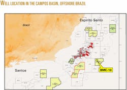
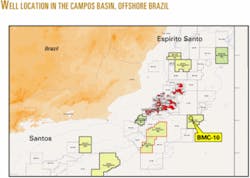
Although surface BOP equipment has been utilized previously, those instances were under relatively benign metocean conditions, primarily in the Far East, and only from moored drilling units. Operations in deep water off Brazil are significantly different and more challenging. The well is in the Campos basin offshore Brazil in Block BM-C-10 and is operated by Shell Brasil E&P, with partners Statoil ASA and Wintershall AG.
The water depths in this block range from about 9,000 ft to deeper than 10,000 ft, with the actual well drilling location in 9,474 ft water. The well was drilled from the dynamically positioned semisubmersible drilling unit Stena Tay using a surface BOP drilling system to more than 17,000 ft TD.
A significant achievement by any measure, but considering the number of records and firsts associated with the project, it was a groundbreaking event for the industry. These achievements include:
- The first deployment of a surface BOP drilling system from a dynamically positioned rig worldwide.
- The deepest water depth well drilled off Brazil.
- The fourth deepest water depth well ever drilled worldwide at the time.
- The deepest water depth drilled by Shell and Stena Drilling.
- The deepest water depth well drilled using surface BOP worldwide.
Key in the success of the project was the support of all participants, including Stena Drilling, Cooper Cameron Corp., Nautronix PLC, Oceaneering International Inc., and Weatherford International Ltd., companies which designed and supplied the BOP equipment and control systems.
Shell is now evaluating the results of the well and considering potential development options in these water depths using surface BOP operations as a key enabling technology.
Background to surface BOP
The surface BOP drilling system is a relatively new application of existing technology and equipment in a deepwater environment. The basic method is not new and in fact goes back to the early days of floating drilling. Existing platform and jackup technology, in which the BOP is traditionally directly below the drill floor, was extended to floating vessels in deeper water. Initially, these vessels were simple barges and ships with essentially land rigs on deck.
As water depths began to increase from more than a few tens of feet, a subsea drilling system was developed in which the BOP is placed on a wellhead at the seabed and a large-diameter drilling riser extended back to surface. This became the standard method of drilling from floating rigs, and systems have been developed for water depths of 10,000 ft.
In these extreme water depths, this conventional approach requires very large, heavy-duty drilling rigs. These are required to support the high loads imposed by the marine drilling riser, the weights of very large subsea BOP stacks, and the deck area to store this equipment when moving between drill sites. While the modern fifth-generation drilling rigs are extremely capable and impressive rigs, they are extremely costly to build and operate, resulting in high day rates and high overall well costs for the operator.
Deepwater well costs are so high that many good geological prospects may not justify an exploration well, and many good discoveries are uneconomic to develop. These factors, in general, will tend to reduce activity levels for all industry participants.
In deepwater wells the rig cost is the major portion of the overall well cost. In turn, the well cost is the major portion of the overall field development cost. Smaller, less expensive rigs can effect significant reductions in the cost of exploration wells and field development wells. Reducing rig costs will increase the activity throughout the industry.
Functions
The primary functions of a BOP stack on a rig are for well control in case of a gas kick and to make the well safe if the rig must disconnect the riser from the wellbore.
For well control, a subsea BOP is typically fitted with three to five ram-type preventers, one to two shear/ blind rams, and one or two annular preventers. There are several individual well-control devices to provide redundancy, as components at the seabed cannot be repaired easily and quickly.
On a surface BOP, there are typically two ram-type preventers: one set of shear/blind rams and one annular preventer. Fewer individual components are required as they can be accessed from surface more easily for repair. The well-control functions of a surface BOP system and a conventional subsea BOP system are essentially the same.
For disconnect purposes, a subsea BOP is equipped with one to two shear rams and a riser or LMRP (lower marine riser package) connector. For surface BOP, the same components are provided in a subsea disconnect system. On moored rigs, only one shear ram is required in either system, as only planned disconnections are made in advance of worsening weather, for example.
On dynamically positioned rigs, two shear rams are required to accommodate an emergency disconnect in case of a drift-off or drive-off event when an emergency disconnect system must immediately (within a few seconds) sequence shearing of the pipe, sealing of the wellbore, and disconnect of the riser. For riser disconnects, the functions of a conventional subsea BOP and a surface BOP system are also the same.
Well-control operations are improved in deep water by use of surface BOP systems. There are no long choke-and-kill lines that impose high back-pressure on the wellbore while circulating out a kick and less chance that hydrates will plug the circulating path during well control. The pressure in the riser is controlled during well control and the possibility of uncontrolled gas expansion in the riser is reduced.
The risk of shallow gas traveling above the BOP stack before the BOP can be closed is mitigated. This is particularly important in very deep water where the distance from potential hydrocarbon-bearing intervals is closer to the BOP stack than the BOP stack is to the rig. The smaller active mud volumes are more quickly weighted up to control the well.
There is more redundancy and flexibility when a subsea disconnect system (SDS) and surface BOP (SBOP) are used in combination, as compared to a subsea BOP. When components are out of the wellbore during a trip, the well can be shut-in at surface with the shear/blind rams in case any gas has migrated into the wellbore above the mudline.
Also, the combination of shear rams at the mudline and at the surface ensures that there are never situations where non-shearable components are opposite all the shearing devices at any time.
Basic system comparison
The comparison of a conventional subsea BOP drilling system and a surface BOP drilling system clearly shows the reduction in size, weight, loads, and physical deck area required to drill a well using surface BOP.
The BOP on a conventional system weighs about 300 tons and is handled in a single piece. This requires very large, heavy-duty handling systems.
In surface BOP operation, the SDS weighs about 60 tons and the surface BOP, about 40 tons.
Along with cutting two thirds of the weight, the components are handled individually and need only very modest handling systems as were found on the earliest two piece BOP handling second-generation rigs.
The riser on a conventional system is typically a nominal 21-in. in diameter with almost 1-in. WT. In addition to this, heavy-walled choke-and-kill lines, hydraulic conduits, and mud-circulation lines are required.
To offset the weight of the riser, buoyancy modules are added. While these reduce the weight of the riser when it is deployed, they are in reality made from dense syntactic foam, which adds considerable weight to each riser joint that must be stored on deck and handled to and from the rig floor.
A 75-ft long, deepwater riser joint with buoyancy weighs up to about 25 tons. This requires large open deck areas that can support about 3,000 tons of riser and heavy-duty bridge cranes to handle it to and from the rig floor.
By comparison, the riser in surface BOP drilling is essentially standard wellbore casing with premium connections. Joints of this riser, which may be from 103/4-in. up to about 16-in. in diameter, depending on the well program, will weigh less than 1.5 tons/40-ft joint for a total string weight of less than 400 tons. These joints can be easily stored on standard pipe racks and handled with standard revolving deck cranes.
The net result of these and other factors is that for drilling in 10,000 ft water depth, conventional subsea drilling techniques call for a fifth-generation drilling rig at a cost of perhaps $200,000/day. Using surface BOP techniques, the 10,000 ft water depth well can be drilled using a third or fourth-generation drilling unit with a day rate of perhaps half that of the fifth-generation rig.
For the future, this technology will allow more rig contractors to compete in ultradeepwater with their existing fleets. The benefit to Shell and partners will be lower cost operations, improved development economics and sustainability of our business, safely into the longer term.
The system enabled the water depth capability of the Stena Tay to be increased from 8,100 ft to beyond 10,000 ft at relatively low cost. Similarly, in the future, this equipment will permit the deployment of lower capacity, lower cost vessels (third, fourth generation) for deepwater operations rather than the more costly, large capacity fifth-generation vessels needed to accommodate the conventional subsea BOP and large riser.
We are now also in a position to explore in water depths greater than 10,000 ft using the existing rig fleet by making use of this surface BOP technology.
Advantages of SBOP
Using surface BOP techniques has several advantages over conventional subsea BOP methods. The obvious advantage is the possibility of using smaller and therefore cheaper drilling units to drill the same well.
There is also the opportunity to increase the water- depth capability of existing rigs. This would allow greater participation in the deepwater drilling market for perfectly good rigs that could otherwise not compete because of their size and load-carrying capabilities.
The advantages of drilling wells with smaller, less- expensive rigs would be lost if it were achieved at the cost of poor efficiency. Many of the individual costs that make up the total well cost are time-dependent, such as the rig, supply vessels, ROV rental, and other support services. With surface BOP techniques, drilling the well is actually faster, as it is quicker to deploy and retrieve the riser and associated equipment and the smaller mud volumes in the riser reduces circulation times.
The increased efficiency of surface BOP drilling has a benefit of improved safety. There are fewer heavy and complex pieces of equipment to handle and maintain, which significantly decreases the exposure to risk for personnel. Quantitative risk analyses (QRAs) indicate that risks are equivalent for surface BOP and conventional subsea BOP drilling.
There are also environmental benefits to surface BOP drilling. A smaller rig will use less fuel; there is much less mud required in the active system with fewer chemicals and less waste. In the event of an unplanned disconnect, the release of mud from the riser to the sea is reduced by almost 60%.
Selection for BM-C-10
The BM-C-10 block lies in water depths ranging from about 9,000 ft to more than 10,000 ft. There are very few drilling rigs that can operate in these water depths. It is only in the last 2-3 years that operations have been conducted with conventional subsea BOPs in these depths and still only a handful of wells have been drilled in water deeper than 9,000 ft.
The rigs in the fleet that could be considered as candidates for conventional drilling in these depths are all newly built, large, fifth-generation rigs. Most of these are very large DP drillships. Perhaps there are two DP semisubmersibles worldwide with these capabilities. As there are few such rigs in existence, the day rates are high and availability is limited.
Drilling the BM-C-10 well with surface BOP allowed consideration of several candidate rigs readily available in Brazil for the project. Several alternatives were considered, but the rig that required the least modification to accommodate the surface BOP equipment was the Stena Tay. This rig had worked in Brazil for 2 years prior to the BMC-10 well and was on long-term contract with Shell.
BM-C-10 well design
The BM-C-10 well was a vertical exploration well in 9,474 ft water depth. A 36-in. conductor was jetted in to about 150 ft below the mudline. The surface casing string, set about 2,400 ft below the mudline, consisted of a 133/8-in. casing crossing over to a 20-in. extension below the wellhead. The wellhead system was a conventional 183/4-in. x 10,000-psi system.
Two drilling liners were set: the 95/8 in. about 3,900 ft below the mudline and the 7 in. about 5,500 ft below the mudline. A 6-in. hole was then drilled to TD at about 7,500 ft below the mudline for a total depth of more than 17,000 ft.
SBOP system configuration
The SBOP system for drilling Well 1-SHEL-14-RJS from the Stena Tay was configured to ensure full well control and provide the ability to secure the well and disconnect in an emergency such as loss of station keeping by the rig. The system was designed for an overall working pressure of 5,000 psi.
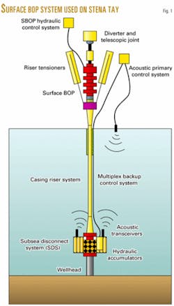
The major components of the system included (Fig. 1): a subsea disconnect system (SDS) at the mudline; a 133/8-in. pressure-containing casing riser; the surface BOP located in the moonpool; and control systems to operate the components:
·Subsea disconnect system (SDS). The SDS provides the functions normally provided by the shear rams and LMRP connector on a conventional subsea BOP stack and consists of the following components:
- 135/8-in. 10M Cameron model-70 riser connector.
- 135/8-in. 10M Cameron type UM single boosted ram preventer.
- 135/8-in. 10M API Fl x Fl drilling spool (51-in. high).
- 135/8-in. 10M Cameron type UM single boosted ram preventer.
- 135/8-in. 10M x 181/2-in.; 10M double-studded adapter.
- 183/4-in. 10M Cameron model HC-H4 wellhead connector.
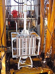
The top riser connector was configured "upside down" from conventional systems (Fig. 2). The body of the connector was positioned on the SDS facing up with a mandrel on the bottom of the riser connecting to it. This had the advantage of keeping all the control functions and hydraulic conduits on the SDS without the need for a hydraulic interface to the bottom of the riser system.
The two ram preventers were configured with shear/blind rams and designed and tested to shear the 51/2-in. drill pipe to be used on the well. A spacer spool between the two preventer bodies was configured to avoid a heavy-wall drill pipe tool joint from being opposite both of the shear rams at any given time.
In this way at least one of the shear rams would be clear of any non-shearable components and able to shear and seal the wellbore in an emergency.
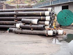
·Casing riser and couplings. The casing riser provides a pressure-containing conduit back to the rig. Any reasonable size casing may be used that suits the well design and pressure-containment requirements. On BMC-10, a 133/8-in. casing riser was selected (Fig. 3) and the system consisted of the following components:
- Upper transition joint connected with an integral Cameron 135/8-in. 10M SSMC wellhead.
- Crossover ACME x casing riser.
- HP casing riser joints.
- Crossover casing riser x ACME.
- Lower transition joint connected with an integral 135/8-in. 10M Cameron model 70 hub.
The upper transition joint provided a heavy-walled transition member between the relatively flexible casing riser and the rigid surface BOP components ensuring a proper distribution of stresses in this region. The top of the transition joint provided a wellhead mandrel to attach the SBOP connector. The transition joint also provided the attachment point for the riser tensioner support ring and tensioner cylinders on the Stena Tay.
At the lower end of the riser, a further transition joint properly distributes stresses in this area and provides a connection mandrel that stabs into the riser connector on the SDS.
The crossover joints between the transition joints and the casing riser allow use of any casing size by simply changing out the crossover. This avoids the need for multiple sizes of transition joint.
For BM-C-10, strakes were installed on the upper 500 ft of the riser to prevent vortex-induced vibrations (VIV).
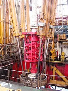
·Surface BOP. The surface BOP provides the well-control functions of a conventional subsea BOP system. Any standard size BOP components can be used, but weight, physical size, thru bore, and the strength of the BOP flanges are all important selection criteria. For BM-C-10, a 135/8-in. three-ram stack with one annular configuration was selected (Fig. 4). This stack is essentially the same as is found on typical jackup drilling units.
The components in the surface BOP stack were as follows:
- 135/8-in. 5M Cameron type DL annular BOP.
- 135/8-in. 10M Cameron type UM single, boosted ram preventer.
- 135/8-in. 10M Cameron type UM double, ram preventer.
- 135/8-in. 10M Cameron fast-lock connector.
The stack was handled on the rig by means of an overhead BOP handling system that was installed under the rig floor of the Stena Tay. A skid cart brought the SBOP towards the well center where it was picked up by the BOP handling system, moved between the riser tensioner cylinders, and landed on the top of the riser upper transition joint.
The connector was made up manually, and the control lines and choke-and-kill flexible lines were attached using conventional goosenecks and stabs. A short, three-barrel telescopic joint, and the original flex joint and diverter at the top provided a conduit for mud returns to the flow line.
·Surface BOP control system. The surface BOP is controlled by direct hydraulic actuation of the individual BOP components. There are a number of methods for adapting an existing rigs subsea BOP hydraulic power unit and accumulator system to operate with a surface BOP.
The Stena Tay was equipped with a multiplex subsea BOP control system; modifying this to work directly with a surface BOP would have been a major exercise. The hydraulic power and accumulators could be easily used for the control fluid however.
The system selected consisted of a standalone hydraulic control manifold supplied with hydraulic fluid from the rig's existing accumulator bank. The manifold directed fluid to the individual SBOP functions via flexible BOP control hoses.
The functions could be manually activated from the control manifold or remotely activated from two electric panels at the drillers control station on the rig floor and in the toolpusher's office.
·SDS control system. The SDS control system had three separate methods of controlling the SDS. The primary system selected was a broadband digital spread-spectrum acoustic control system. This system consists of a main control unit that operates acoustic transponders that transmit acoustic signals to transceivers on the SDS. Subsea control modules on the SDS interpret the signal and direct the appropriate function to actuate.
The main surface transponder was below the hull of the rig in a deployment casing that was attached to the outside of one of the rig's columns. A secondary transponder was at the forward end of the rig mounted on a winch that could lower the transponder below the rig's hull. The transponders were located considering the thruster positions on the rig and protection from mechanical damage.
The secondary system provided electrical signals from the surface transmitted to the subsea control modules by an electric cable that was strapped to the riser. As the SDS is used for sealing the wellbore and disconnecting the riser in emergency only and is not part of the routinely operated well-control equipment, there was no need for a direct hydraulic fluid supply from surface. Piston-type hydraulic accumulators with sufficient capacity to operate the critical functions (close and lock shear rams and unlatch riser) were provided.
Other noncritical functions were controlled by ROV intervention only. The ROV could also operate the critical functions in the event of a complete control system failure providing a third level of redundancy.
Risk assessment
To implement a new technology such as SBOP, it is very important to identify and fully understand the risks and to design the system to eliminate or mitigate risks.
The intended operation of the equipment must be thoroughly thought through with appropriate procedures and safeguards in place.
This risk-assessment process is a significant effort in the planning and implementation of a surface BOP system, particularly for the first time. Operators and drilling contractors considering SBOP solutions should not under estimate the level of effort required.
For the BM-C-10 well, Shell began with a HAZID (hazard identification and risk assessment) exercise.
This was a 1-day workshop for experienced engineering, operations, and other personnel to identify potential hazards.
A quantitative risk assessment was performed in order to understand and compare the magnitude of the risks and to study the risk associated with different failure modes. A technical limit workshop, in which all personnel associated with the project participated, reviewed in detail the technical solution being proposed.
Several specialized studies were performed, including acoustic control system reliability, a comparison of surface and subsea BOP risks in deep water, riser analysis, VIV studies, and riser recoil studies.
A second technical limit workshop involved people responsible for delivering the well. This "drill the well on paper" exercise was conducted in Brazil and generated many suggestions and improvements. A HAZOP (hazard and operability studies) exercise reviewed the SBOP operational details including well-control procedures.
During the manufacturing process, a rigorous third-party inspection program ensured all components met the required specifications that would allow the equipment to perform as intended.
Initial deployment
The well was drilled in 53 days, including about 15 days of nonproductive time. This was divided fairly evenly between "teething" problems associated with the new SBOP equipment and problems associated with drilling the well, which encountered significant losses of mud to the formation.
After initial deployment of the SBOP equipment, difficulties were encountered with the operation of one of the rams. The cause was a problem in the pressure-balance system and was rectified by physically cutting the balance system exhaust hose using the ROV.
Some further time was lost when the seals on the ROV stab, used to charge and operate the system, were damaged.
These minor events were corrected, but after full function-testing of the SDS, a rupture disk in the control system failed, causing a complete loss of accumulator pressure at the SDS.
The riser and SDS had to be pulled, the rupture disk repaired, then the equipment re-run. This accounted for the majority of the downtime due to SBOP-related issues. These difficulties were seen as teething problems associated with initial operation of the equipment in the field.
On the positive side, the rig crew gained more experience in handling the equipment and the riser. The riser running time improved significantly on the second run and was better than the best-expected time for a subsea BOP. More experience in operating the system has led to further improvement.
Ongoing, future work
Implementation of this technology is now being executed globally. Following completion of the Brazil well, the equipment traveled with the Stena Tay to Egypt to carry out a three-well exploration campaign in water depths greater than 8,000 ft. The well designs for these wells were similar to the first well in Brazil, although the 7-in. liner was not run.
The Eastern Mediterranean had a very rough winter this year, with several storms passing through. The tolerance to wind and waves for the SBOP system proved to be comparable to conventional systems. A planned disconnect was carried out once, and the riser and control cable were successfully reconnected after the weather had calmed.
Following the three wells in Egypt, planning is under way for potential use of a surface BOP system on a large multiwell field development in West Africa, as well as potential field developments in other areas.
Guidelines, standards
As with any new technology, there are usually few or no guidelines or standards to follow when the technology is implemented. Surface BOP technology is no exception in this regard.
While there are numerous existing standards and guidelines for conventional drilling operations that cover elements of SBOP system design, configuration, and operation, there are at present no SBOP-specific guidelines. The approach to SBOP operations within the industry has been somewhat inconsistent, driven by specific circumstances, rather than by broadly accepted best practices.
The International Association of Drilling Contractors (IADC) is seeking to rectify this and has taken the initiative in developing a set of SBOP specific guidelines for use by the drilling industry. The efforts started in November 2002, when the IADC hosted a conference on surface BOP drilling.
In this first event of its kind, attended by more than 250 delegates from industry and government, information, knowledge, and concerns were shared in a series of formal presentation and workshop breakout sessions.
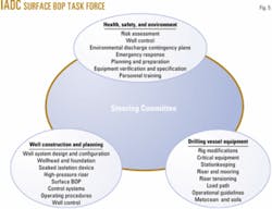
An IADC task force was assembled and an initial meeting held in February 2003. The mission of the task force is to develop a set of guidelines to aid the drilling industry in planning and conducting surface BOP operations on floating mobile offshore drilling units using existing best practices and the experience and study of the contributors developing them.
The guidelines are to give the drilling industry a basis for future deepwater surface BOP operations worldwide. The task force assembled three working groups or subcommittees of industry professionals, and the work is directed by an overall IADC steering committee (Fig. 5).
As of January 2004, the subcommittees had assembled complete draft documents in each of the three main areas of study. These are now under review by the subcommittees and steering committee and will be compiled into a comprehensive set of guidelines available to the industry later this year.
The authors
Graham Brander ([email protected]) is the deepwater well engineering manager at Shell International E& P Inc., Houston. He has also served as the surface BOP team leader for Shell Deepwater Services and held various other well engineering and operations roles within Shell in the last 8 years. Prior to joining Shell, Brander was employed by Unocal Corp. in various international locations as a well engineer. He earned a BSc Hons (1985) in civil engineering from Edinburgh University and is a member of the SPE.
Jim Adam ([email protected]) is manager of deepwater well delivery for the Americas region at Shell International E&P Inc., Houston. Adam joined Shell in 1974, following a post as lecturer in physics at Robert Gordon Institute of Technology in Aberdeen. He has held several senior positions within the company in well engineering, economics, and technical support, in Europe, South America, the Middle East, and North America. Adam holds a Graduateship of the Institute of Physics degree fromNapier College, Edinburgh. He is an SPE member, a Fellow of the Institute of Materials, Minerals and Mining, and a chartered engineer.
