Revamp improves FCC performance at BP's Texas City refinery
In early 2003, BP Products Co. revamped its Texas City, Tex., refinery. Changes to FCC Unit 1 reduced the true boiling point distillation curve's 90%-final boiling point tail for the heavy catalytic naphtha (HCN) to 36° F. from 58° F., lowered gasoline sulfur content,1 and improved gasoline recovery from the light catalytic cycle oil (LCCO) by 800 b/d.
Since the 2003 revamp, the unit has processed 60,000 b/d of feed at maximum conversion, which it could not do before the turnaround. Heat and material balance principles, field data gathering and interpretation, and packed-column internal design basics were critical to the success of this revamp.
Finding opportunities
BP's Texas City refinery has three FCC units that have been modified several times since their original installation more than 50 years ago.
After BP replaced trays in the FCC Unit 1 main column with structured packing in 1999, fractionation degraded, which lowered HCN product yield and increased HCN sulfur content.
In 2002, BP evaluated possible scenarios that would improve profitability, eliminate operating constraints, and reduce FCC gasoline sulfur content.
The first step in developing a good business case is to identify underutilized or poorly performing equipment. Achieving real gains demands that one identify root-cause shortcomings (OGJ, May 31, 1993, p. 54; Dec. 25, 1995, p. 75).2-4
A logical approach5 begins with the determination of what field testing is needed. Engineering and operating personnel can then gather necessary data. Only then can one develop accurate process and equipment modeling. Even perfect execution of an improper process or faulty equipment design will not meet business revenue targets.
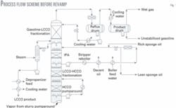
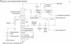
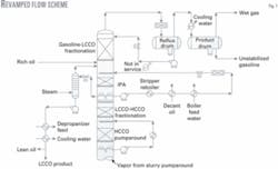
Fig. 1 shows the main fractionator process flow scheme before the 2003 revamp. A review of the existing process flow scheme showed that the heat balance was flawed because sufficient heat removal was unavailable above the LCCO product draw. This resulted in a periodic loss of level in the LCCO product stripper.
In the summer, total condenser plus subcooler heat removal was insufficient at high feed rates and maximum conversion. Heat removal did not allow stable control of LCCO product yield because the LCCO product was withdrawn from above the intermediate pumparound (IPA).
Isolating the root cause of poor performance requires suitable field data gathering and testing procedures. Pressure and temperature measurements are essential tools with particular requirements depending on equipment and symptoms.
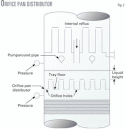
For example, if a packed column's pressure drop periodically increases with higher pumparound flow rates and the column uses orifice pan distributors (Fig. 2), then measuring pressure drop across the distributor may help pinpoint the problem.
Liquid flows through holes in the tray floor and vapor flows through the risers. Measured pressure drop across an orifice pan distributor does not change as the liquid rate increases until the height reaches the top of the vapor risers. At this point, measured pressure drop increases proportional to the height of liquid over the top of the vapor risers.
Because liquid flow rate through orifice holes depends on head (level) over the holes, the fluid height above the top of the risers will increase until the available head is sufficient to meet the increased liquid rate. Once the liquid level reaches the top of the riser, however, it becomes aerated with riser vapor. The true froth height is greater than the measured change in pressure drop indicates, assuming constant liquid density.
As the pumparound rate increases, measured pressure drop will increase as the froth height builds. Eventually, IPA liquid is carried up the column and causes flooding.
Skin temperature measurements at the same elevation around the vessel circumference are another useful troubleshooting tool.6 Large temperature variations imply some type of distribution problem, which includes inadequate mixing of internal and pumparound return liquids.
Temperatures around a column's circumference will be uniform given perfect distribution. In BP's case, radial temperature measurements helped pinpoint the problem.
Replacing trays with packing can increase capacity, improve fractionation, and reduce pressure drop. These types of revamps, however, are more challenging to design and install properly.
Common problem areas with packing include nonuniform liquid distribution, poor vapor distribution, and inadequate mixing of pumparound return streams with the internal liquid.
Uniform liquid distribution provides the same amount of liquid for each cross-section in the column. This is an important design criterion, but alone it is insufficient to ensure good fractionation in a packed column.
Another concern is reactor-effluent vapor distribution. When a column is completely packed, low-pressure-drop internals do not correct poor initial vapor distribution. BP's column had a valve tray below the HCCO pumparound that generated high pressure drop; therefore, vapor distribution was not a significant concern.
A frequently overlooked consideration is mixing of internal liquid with the pumparound stream.7 Good mixing is absolutely critical for a packed column. In this case, radial temperature surveys at three elevations helped identify potential problem areas.
Heat balance
The fractionator heat balance influences product fractionation because it controls internal reflux. It also affects operating stability, especially when product and pumparound streams are withdrawn at different elevations; the product draw can sometimes withdraw all available liquid, which eliminates the reflux below the draw.
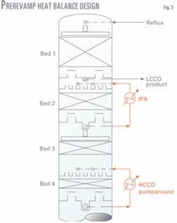
Fig. 3 shows the LCCO and IPA draw arrangement before the 2003 revamp. LCCO product was withdrawn above the IPA return.
Operations were stable as long as there was sufficient heat removal above the LCCO product draw to meet the product yield and allow some reflux to overflow the draw tray. LCCO stripper level was lost, however, when the total IPA, HCCO, and slurry pumparound heat removal was high enough to reduce internal reflux to zero (OGJ, Apr. 7, 1997, p. 62; Apr. 14, 1997, p. 47).
If the LCCO product and IPA pumparounds are at different locations, this will increase the IPA draw temperature, which reduces IPA flow rate and exchanger surface area to meet the heat removal target. Although it lowers investment cost, this process flow scheme is impractical when heat removal above the IPA circuit is inadequate to generate internal reflux at the LCCO product draw.
Condenser capacity is expensive; operators must therefore reduce the reflux flow rate when the charge rate, conversion, feed nozzle atomizing steam rates, and ambient air temperature increase.
In this case, the top reflux rate and reflux subcooler duty was not high enough during warm weather to meet the LCCO product rate and allow some internal reflux flow from the product draw tray. Condenser limits and chronic problems with the cooling water supply to the reflux subcooler caused rapid exchanger fouling, which lowered subcooler duty.
During warm weather, BP increased the total slurry, HCCO, and IPA duties, which lowered the top reflux rate and internal reflux from the LCCO product draw. Once the internal liquid rate from the LCCO product draw tray reached zero, the product side-stripper lost level because the stripper bottom product flow controller was attempting to withdraw more LCCO product than was available as stripper feed.
The stripper liquid level was periodically lost, resulting in cavitation in the LCCO product pump. The operator, therefore, could not independently adjust the product flow rate because it depended on the main column heat balance.
A further review of the heat balance showed that a small portion of the IPA circulating stream was used for sponge absorber lean oil and post-riser quench, and rich oil from the sponge absorber was combined with the IPA return stream. Because lean oil is cooled with air and cooling-water exchangers, this duty becomes part of the main column heat balance.
Sponge absorber rich oil contains C2-C6 hydrocarbons, which vaporize at lower pressures and column temperatures. Before the revamp, the IPA return temperature was only 135° F. leaving the fin-fan exchangers; consequently, only a small portion of the rich sponge oil vaporized when it combined with the IPA stream before entering the column. But when the IPA return entered the column and flowed across the orifice pan distributor, the light components vaporized rapidly.
Moreover, when the column heat balance generated hot 420° F. internal reflux that fed the IPA distributor for Bed 2, severe vaporization occurred where these streams mixed.
BP also used part of the IPA stream as post-riser quench to reduce the reactor temperature 25-50° F. depending on reactor severity targets. The quench rate increases even more as the reactor temperature rises, which further increases main column heat-removal requirements.
Temperature, composition gradient
Properly designed packed-column internals generate small radial temperature differences because composition variations are small. Yet, when radial temperature measurements show large variations, liquid and vapor distribution problems degrade fractionation. Because radial temperature measurements above IPA Bed 2 varied 84° F. from the high to low readings, distribution problems obviously caused the poor fractionation.
Table 1 shows that the measured radial skin temperatures above gasoline-LCCO Bed 1, IPA Bed 2, and above the LCCO-heavy catalytic cycle oil (HCCO) Bed 3 varied 64º F., 85º F., and 48º F., respectively.
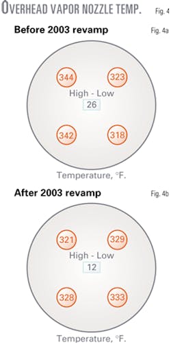
BP's main column was atypical because it had four outlet nozzles on the top head. During field testing, the temperature difference between the four nozzles was 26° F. (Fig. 4a). In other operating modes, the temperature difference increased to 35-40° F.
The 26° F. difference was due to a large composition gradient that reached the column's top through the gasoline-LCCO fractionation bed, which had more than 11 ft of packing. A detailed review of the column internals design was therefore needed to determine root cause problems.
Packed-column fundamentals
Packed columns use liquid distributors to distribute liquid and collector trays and vapor distributors to distribute vapor streams. Packings' inherent distribution quality will create maldistribution even if the initial distribution to the bed is perfect. Some radial temperature and composition gradients, therefore, always exist above and below a packed bed.
Packing will not correct poor initial liquid or vapor distribution, or compositional gradients. Once initiated, maldistribution and gradients propagate throughout the packed beds. Process engineers must be aware of all the factors that influence packed-bed distributor performance.
Ideally, each cross-sectional area of the packed bed should have uniform liquid and vapor compositions and rates; otherwise, parts of the bed will have different liquid:vapor ratios and compositions. In one case, a poor distributor design caused parts of a bed to be nearly dry, which resulted in poor fractionation measured by 95%-5% distillation temperature differences between adjacent products.
BP's HCN 95% temperature and LCCO 5% temperature were 400° F. and 391° F., respectively. There was, therefore, a 9° F. overlap between HCN and LCCO products that resulted in an apparent gasoline-LCCO bed fractionation-bed efficiency of only one theoretical stage. The apparent height equivalent to a theoretical stage was more than 11 ft.
An inexperienced designer might assume a solution of a deeper bed of packing or higher-efficiency packing to improve fractionation. This would marginally increase efficiency, but adding 40% more packing generates only 1.4 theoretical stages. Assuming good distribution, an 11-ft packed bed should have at least 3.5-4 theoretical stages. Finding the root cause of underperformance is the key to meeting fractionation goals.
Three radial temperature surveys at different elevations showed the variation was worse above the IPA's liquid distributor.
The IPA's pumparound liquid distributor was therefore a likely contributor to poor fractionation.
Pumparound liquid distributors must mix internal liquid with pumparound streams so that the composition and temperature of liquid to the pumparound packed beds are uniform.
Because pumparound beds condense some of the entering vapor, condensation should be uniform across the column. Otherwise, the composition and temperature of the vapor and liquid leaving the bed will not be uniform.
The IPA and HCCO pumparounds both used orifice pan distributors. Composition gradients existed because these distributors did not mix the pumparound and internal liquids.
The large radial temperature variation above the IPA distributor was not a surprise.
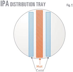
A detailed review of the IPA distributor (Fig. 2) operation showed that internal reflux from the LCCO product collector fed onto the middle of the orifice pan distributor, while the IPA return stream was fed by two off-center pipes.
A liquid with nonuniform composition and temperature was consequently distributed across the IPA packed bed causing poor apparent fractionation in the bed above.
Fig. 5 shows the hot (red) and cold (blue) liquid streams that feed different sections of the orifice pan distributor. The red box is the lone central downcomer from the LCCO product collector draw tray. The two outside blue boxes are 135º F. cold pumparound return liquid.
Gasoline-LCCO fractionation varied depending on IPA flow rate and whether the heat balance generated internal reflux. The pan distributor, however, did not mix the hot and cold liquids except along the edge of the LCCO collector tray downcomer.
IPA duty was more than 50 MM- btu/hr and the pumparound condensed a large amount of vapor. The hot internal reflux still had little heat-removal capability; most condensation occurred where the cold IPA return stream flowed into the packing. Vapor leaving the central zone was therefore hotter and had a much higher end point than vapor leaving the packing above areas where cold IPA liquid was distributed. This high-end-point material entering the gasoline-LCCO bed degraded fractionation.
Low IPA distributor capacity also reduced fractionation. When IPA flow rate increased to 23,000 b/d during a field test, the column pressure drop increased, which resulted in poor gasoline-LCCO fractionation.
Flooding occurred at high IPA flow rates because the liquid level reached the top of the orifice pan's distributor risers and IPA liquid carried up the column into the gasoline-LCCO fractionation bed.
Distributor liquid handling capacity was much less than expected because the IPA stream contained rich sponge oil that vaporized on the distributor. When this light material vaporized, it caused extreme frothing and turbulence on the tray, which reduced its capacity. A column gamma scan confirmed the distributor flooding.
Other fractionation factors
Localized temperatures dropped below the bulk water dewpoint when 135° F. IPA pumparound and 115° F. subcooled top reflux contacted the ascending vapor, which formed a localized free-water phase. Cleaning the reflux subcooler lowered the reflux temperature to about 115° F. from 190° F., thereby inducing localized water condensation to form a free-water phase in the top section of the gasoline-LCCO fractionation bed.
Cold reflux and condensed water had to be heated above water dewpoint before meaningful fractionation occurred. The top 36-48 in. of the packed bed provided heat transfer, but little fractionation.
Revamp heat balance
Meeting business objectives mandated changes to the process flow scheme and column internals8 9 to address root cause flaws.
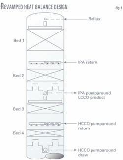
Heat balance changes included removing the reflux subcooler to raise reflux temperature and avoid water condensation in the top section of the gasoline-LCCO bed and combining the LCCO product and IPA draw locations (Fig. 6).
Removing the reflux subcooler lowered overhead cooling by about 10 MMbtu/hr, which reduced internal reflux in the column's gasoline-LCCO section. Combining the LCCO and IPA draws improved operability.
This increased heat removal above the LCCO draw and eliminated dry-out of the reflux that had caused periodic cavitation in the stripper bottoms product pump.
Moving IPA heat removal to join the LCCO draw allowed IPA duty to generate the required internal reflux to meet LCCO distillation targets. It also, however, lowered the IPA draw temperature to 450° F. from 530° F. The IPA circulation rate had to increase to 25,000 b/d from 17,300 b/d to meet heat removal requirements.
BP increased the IPA return temperature to 190° F. to eliminate localized water condensation in the tower.
The lean sponge oil withdraw point was changed to the LCCO product circuit from the IPA circuit to maximize the IPA circulation rate with the existing pump to meet IPA duty targets. This required only minor piping changes. Moving lean sponge oil to LCCO rundown circuit allowed an increase of 2,100 b/d in IPA circulation and raised IPA duty 9%.
Fig. 7 shows the modified process flow scheme.
Column internal modifications
IPA and HCCO pumparound orifice-pan distributors were removed because they contributed significantly to poor fractionation. Both distributors were replaced with spray distributors, and the internal reflux was allowed to fall directly on the packing in pumparound Beds 2 and 4.
The rich sponge oil return stream returned to the column at the same elevation as the IPA return, but a separate distributor was used because this is a two-phase stream.
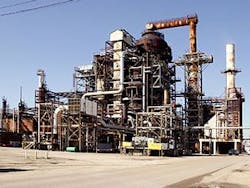
After revamping this FCC unit in its Texas City refinery in 2003, BP can now process 60,000-b/d of feed at maximum conversion. Photo courtesy of BP Products Co.
No additional packing was added to the gasoline-LCCO fractionation bed. The HCN-LCCO product 95%-5% overlap of 10° F. improved to a gap of 26° F. and a postrevamp audit showed that the bed generated almost four stages of fractionation.
Additionally, the HCN 90%-final boiling point tail improved to 36° F. from 58° F., thereby lowering gasoline sulfur. A large portion of FCC gasoline sulfur is contained in heavy ends.
Revamp results
Real gains require that one identify and correct the root-cause problems; otherwise business targets cannot be met. In this case, heat balance and column internals changes were needed.10-13 First, appropriate field data were gathered, followed by process and equipment modeling.
Fig. 4 shows the measured vapor temperatures leaving the four overhead vapor nozzles before and after the 2003 revamp. Before the revamp, vapor temperatures varied 26° F. and increased to as much as 35-40° F. during some modes of operation.
After the revamp, temperature variation decreased to 12° F.
Gasoline and LCCO fractionation improved due to the heat balance and column internals changes. Column maldistribution and compositional gradients were greatly reduced due to removing the IPA orifice-pan distributor, installing a spray header, and allowing the internal liquid to fall directly onto the IPA packing.
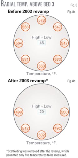
Radial temperatures measured above Bed 3 had less variation—to 20° F. from 48° F. (Fig. 8). Composition gradients generated from the HCCO pumparound orifice-pan distributor were greatly reduced. Temperatures were lower after the revamp because of the heat balance shift.
References
1. Golden, S., Hanson, D., and Fulton, S., "Use better fractionation to manage gasoline sulfur concentration," Hydrocarbon Processing, February 2002, pp. 43-46.
2. Hartman, E.L., Hanson, D.W., and Weber, B., "FCCU main fractionator revamp for CARB gasoline production," Hydrocarbon Processing, February 1998, pp. 44-49.
3. Barletta, T., "Pump cavitation caused by entrained gas," Hydrocarbon Processing, November 2003, pp. 69-72.
4. Lieberman, N., and Hanson, D., "Vacuum Unit Troubleshooting," Petroleum Technology Quarterly: Revamps and Operations, Autumn 2003, pp. 22-25.
5. Golden, S., Moore, J., and Nigg, J., "Optimize revamp performance with a logic-based approach," Hydrocarbon Processing, September 2003, pp. 75-83.
6. Golden, S.W., "Revamping FCCs – Process and Reliability," Petroleum Technology Quarterly, Summer 1996, pp. 85-93.
7. Torres, G., Waintraub, S., and Hartman, E., "Crude Unit Revamp Using Radial Temperature Profiles," Petroleum Technology Quarterly: Revamps and Operations, Autumn 2003, pp. 12-14.
8. Golden, S.W., et al., "FCC main fractionator revamps," Hydrocarbon Processing, March 1993, pp. 77-81.
9. Golden, S.W., "Approaching the Revamp Project," Petroleum Technology Quarterly, Autumn 1995, pp. 47-55.
10. Barletta, T., Smith, M., and Macfarlane, C., "Crude Unit Revamp Increases Diesel Yield," Petroleum Technology Quarterly, Spring 2000, pp. 45-51.
11. Hanson, D.W., and Hartman, E.L., "Gas Plant Revamps for Higher Capacity and Efficiency," Petroleum Technology Quarterly, Summer 2000, pp. 69-75.
12. Hartman, E.L., and Hanson, D.W., "Reboiler Behind Distillation Tower Problems," Petroleum Technology Quarterly, Spring 2001, pp. 111-117.
13. Hanson, D.W., and Becker, T., "Revamped FCC debutanizer yields flexibility with more capacity," Hydrocarbon Processing, August 2002, pp. 79-84.
The authors
Scott W. Golden (SGolden@ Revamps.com) is a chemical engineer with Process Consulting Services Inc., Houston. His previous experience includes refinery process engineering, and distillation troubleshooting and design. He holds a BS in chemical engineering from the University of Maine and is a registered professional engineer in Texas.
Daryl W. Hanson (DHanson @Revamps.com) is a chemical engineer with Process Consulting Services Inc., Houston. His experience includes lead process specialist for Koch-Glitsch Inc., Dallas, where he was involved in more than 100 column revamps including heavy oils and light-ends recovery. Hanson holds a BS in chemical engineering from Texas A&M University.
Joy Hansen is operations superintendent for FCC Nos. 1 and 2 at BP Products Co., Texas City, Tex. She has also served as technical liaison for Cypress Minerals Corp. and research engineer for Amoco Oil Co. Hansen holds a BS degree in chemcial engineering from the Colorado School of Mines.
Mike Brown is the asset coordinator for FCC Nos. 1 and 2 at BP Products Co., Texas City, Tex. He has 25 years' experience in refinery operations for Amoco Oil Co. and BP PLC. Brown holds a degree in environmental technology from Southern Illinois University.
