Acid-gas injection design requires numerous considerations
LISBON GAS PLANT—Conclusion
The design of an acid-gas injection system requires numerous design considerations, as shown in this second of two articles on the Lisbon gas plant, Moab, Utah.
This part covers the design and operation of the compression and injection portions of the facility. The first part (OGJ, Mar. 1, 2004, p. 54) discussed the acid-gas enrichment portion with emphasis on the Flexsorb selective amine-treating unit.
Acid-gas injection
Fig. 1 shows the block-flow diagram for the acid-gas injection (AGI) unit. Enriched acid gas from the Flexsorb regenerator is mixed with methyldiethanolamine (MDEA) raw acid-gas feed that was bypassed around the Flexsorb treating unit.
The resulting blended acid-gas mixture flows to the suction of the injection compressors. Blended acid-gas composition varies from 32% to 38% H2S (plus CO2 and water).
High-pressure blended acid gas flows from the compressor discharge through the pipeline to the wellsite, into the wellbore, down the well tubing, and finally into the reservoir.
Acid-gas injection compressors
null
The two injection compressors operate in parallel and compress 0.5-1.0 MMscfd each, depending upon suction and discharge pressures. Capacity control is limited to an adjustable pocket on the first stage of compression.
Metallurgy for all compressor piping, gas cooler, and scrubbers is 304L stainless steel. The compressor cylinders are carbon steel or "gray iron." The transition from stainless to carbon steel is the entrance to the pipeline following the discharge from the fifth stage.
The double-distance piece on each throw and the packing on each stage are purged with nitrogen.
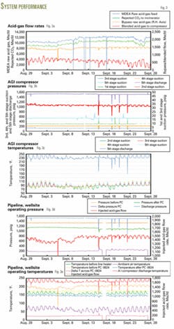
The combined total flow rate from the injection compressors averages 1.5 MMscfd (Fig. 3a).
Flow rate of enriched acid gas (50% H2S) from the Flexsorb regenerator is about 1.0 MMscfd; therefore about 0.5 MMscfd of the MDEA raw acid-gas feed (4-5% H2S) bypasses around the Flexsorb treating unit.
The bypass is intended to keep the compressors fully loaded and maintain constant suction pressure control. Bypass flow rate can reach 100% of the compressor capacity at times such as start-up. The compressors are started up with MDEA raw acid gas.
Injection into the wellbore continues until the entire system warms up to normal operating temperatures. After that, the flow of enriched acid gas from the regenerator starts.
Compressor performance
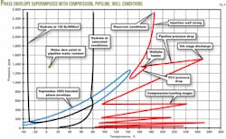
Fig. 4 shows the compressor interstage pressure profile design with the phase envelope based on the enriched acid-gas composition. Fig. 3b shows actual compressor interstage suction scrubber operating pressures. Also shown is the trend of the fifth-stage discharge pressure, about 1,500 psig.
The design limits the compression ratio for each compression stage to keep the discharge temperature below 300° F. (upstream of the coolers).
Variable-speed motors installed on the compressor's gas coolers reduce the variation in outlet temperature (suction temperature for the next compression stage). Fig. 3c shows actual compressor interstage suction-scrubber operating temperatures.
Normal operations bypass the compressor's fifth-stage gas cooler so that the high-pressure blended acid gas discharges into the pipeline at about 240° F. (Fig. 3c). It is important to maintain operating pressures and temperatures so that the blended acid gas does not enter the two-phase envelope.
Entering the two–phase region would cause liquid acid gas to form, which is undesirable in the compressors, pipeline, or wellbore under normal operating conditions.
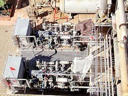
Each injection compressor is a five-stage, six-throw Ariel Model JGA/6 compressor with five double-acting cylinders and no tandem cylinder. The driver is a 250-hp electric motor operating at 1,200 rpm (Fig. 2).
Liquid water condensed in the interstage coolers, particularly the second, third, and fourth stages, collects in the suction scrubbers.
Compressor lube oil also collects in the suction scrubbers. Level controllers on these scrubbers allow liquid flow to cascade in sequence from the high-pressure scrubbers to the inlet scrubber.
The liquids in the inlet scrubber are pumped to the sour-water handling system. These liquids have been a problem to pump and handle in part because the lube oil and water form a white foamy emulsion.
High levels and level instrument failures in the scrubbers have caused numerous compressor shutdowns. The float indicator in a level instrument does not work well when the liquid in the scrubbers is an emulsion.
Water content
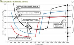
The fifth-stage suction conditions are key to successfully dehydrating the blended acid gas using the compression cycle. Fig. 5 shows water content of the enriched acid gas from the regenerator as a function of pressure and temperature.
Water content of the blended acid gas should be analogous. Water content of saturated acid gas is high at low pressure, but as the pressure approaches 500-1,000 psig, the water content goes through a minimum then rapidly increases again as pressure increases. This acid-gas characteristic has the advantage that one can achieve partial dehydration of the acid gas during compression.
As pressure increases in the first four stages, water content drops continuously until the fifth-stage suction where it hits the minimum, about 125 lb/MMscf at 100° F. The fifth-stage of compression increases the pressure to more than 1,500 psig where the acid gas can now hold much more water, about 500 lb/MMscf at 100° F., before reaching saturation.
The fifth-stage suction temperature determines the water content of the blended acid gas in the pipeline and wellbore. The cooler the temperature of the fifth-stage suction, the lower the water content. The lower the water content, the better the protection against water condensation and hydrate formation in the pipeline and wellbore.
The fifth-stage suction temperature varies from 80° F. to as much as 110° F. (Fig. 3c). The swing is due to changing ambient air temperature and the gas coolers. When the fifth-stage suction temperature is 100° F., the corresponding water dewpoint temperature of the compressed enriched acid gas is 5° F. (Fig. 5).
When the fifth-stage suction temperature swings to as low as 80° F., the corresponding water dewpoint temperature of the compressed enriched acid-gas is 0° F. This means that the temperature of the enriched acid gas following the fifth stage of compression, in the pipeline or wellbore, would have to fall to +5° F. or 0° F. before water could condense.
At these temperatures any water that did condense out would actually form ice. The ice might not cause corrosion immediately but would eventually become a problem when temperature increased at the wellsite or in the injection wellbore.
Liquid water in the carbon steel piping in the pipeline, wellsite, or in the wellbore could cause severe and rapid corrosion. The fifth-stage compressor discharge flows hot into the entrance of the insulated pipeline to take advantage of the heat of compression. This serves to maintain the blended acid-gas temperature in the pipeline well above the point where free water, ice, hydrates, or liquid acid gas might form.
Corrosion inhibitor is injected into the high-pressure blended acid gas at the discharge of the compressors continuously but at a low flow rate of about 1 qt/day just for good measure.
Design considerations
The design basis governs the operation of the facility to ensure that the high-pressure blended acid gas is safely contained and disposed of. The specified operating conditions will prevent condensation of water or liquid acid gas at any point in the system. The plan calls for operation above the critical point and also at temperatures greater than the water dewpoint and hydrate point, at all times.
Washington Group International prepared phase envelopes and physical property predictions describing the behavior of the acid gas during compression, transmission, and injection for numerous operating scenarios, including start-up and shutdown.
The peculiar nature of supercritical acid-gas mixtures must be carefully considered to account for significant and unusual changes in density, viscosity, heat capacity, and thermodynamic behavior.
As shown in Fig. 4, the wellsite and wellhead operate particularly close to the critical region where physical properties (such as density) can vary widely with small changes in temperature and pressure.
This could lead to instability; so, considerable effort is made to stay out of this thermodynamic region. Fortunately, the phase envelope and critical region for acid gas shifts left (relative to that shown in Fig. 4 for enriched acid gas) when MDEA raw acid gas is blended with the enriched acid gas from the regenerator.
Blending the two acid gases reduces the H2S content, which shifts the phase envelope toward cooler temperatures. Shifting the phase envelope moves the critical region further from the normal operating conditions for the pipeline and wellsite.
High-pressure pipeline
null
Elevation at the plant is 6,000 ft above sea level, and the wellsite is 300 ft higher than the plant. The pipeline route twists and turns back and forth and up and down as it snakes its way along an intermittent streambed.
The pipeline is 2-in. OD Schedule 160, API X-42, 0.343-in. WT carbon steel pipe. Pipeline maximum allowable pressure is 2,150 psig that is limited by the stainless steel flanges on the compressor discharge.
Compressor high-pressure shut down is 90% of the maximum pressure or 1,935 psig. Maximum operating temperature is 350° F.; although normal operating temperature is less than 300° F. The pipeline has a 0.72 location class factor. Corrosion allowance is 0.25 in., which is over and above the wall thickness required to contain the maximum pressure.
The pipeline was designed according to ASME Code B31.8 outside of the plant boundary. It has a corrosion probe installed at Well B-624. Two H2S monitors, supervisory control and data acquisition (SCADA) operated, are along the pipeline route in addition to H2S monitors at the plant and B-624 wellsite.
All H2S monitors alarm in the plant's control room. Welding procedures were according to NACE MR-01-75, and 100% of the welds were X-ray inspected.
To retain heat, a 2-in. black fiberglass foam insulation covers the pipeline. The pipeline lies on the ground supported by and clamped to wooden blocks at 10-15 ft intervals. Expansion loops are installed in key areas to minimize thermal pipe stress.
The pipeline shifted its position in numerous places upon start-up due to thermal expansion.
Thermal expansion ranges from 1.5 to 3.0 in./100 ft, or as much as 22 ft of total change in length over the 2.5 mile distance.
The design concept allows the pipeline to move with temperature changes because there is sufficient room to wiggle in the numerous turns of the circuitous route.
For more than 27 years, the operators injected sour gas (1.1% H2S, 25% CO2 plus hydrocarbons) compressed in the plant back into the reservoir via gas-cap injection wells.
During this time, they observed that it was a good practice to allow the surface injection pipelines to move around as necessary to accommodate thermal expansion.
The installation allows for the purging of the acid-gas pipeline by the compressors with methane fuel gas in order to remove the blended acid gas. The compressors have a maximum allowable operating pressure of 1,935 psig, which is below the injection pressure needed to displace either nitrogen or methane fuel gas fully into the reservoir.
The specific gravity of nitrogen or methane is less than that of the blended acid gas; therefore wellhead injection pressure is correspondingly higher. However, fuel gas will displace the blended acid gas to the wellhead and down into the wellbore some distance. At this point the wellhead valves can be closed, effectively removing the blended acid gas from the pipeline.
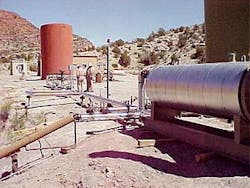
The high pressure, acid-gas pipeline originates at the compressor discharge in the Lisbon plant yard, then winds through a red-rock canyon for 2.5 miles before reaching the injection well (Fig. 6).
null
Methane fuel gas should not normally be mixed with the blended acid gas to be compressed and injected into the well.
Fuel gas increases the water dewpoint temperature of the acid gas, which increases the chance that water will condense.
Fuel gas is used only to displace the acid gas in the pipeline into the wellbore but then the fuel gas is blown down.
If both compressors are shut down for more than a few hours during very cold weather, the operators can displace the blended acid gas into the wellbore with fuel gas. The fuel gas is then blown down to evacuate the pipeline.
Injection wellsite
The pipeline ends are on the injection wellsite at the inlet to a wellhead heater (Fig. 7). Pressure at the compressor discharge, about 1,500 psig, has declined to about 1,350 psig (no less than 1,300 psig) at the wellsite (Fig. 3e).
Pressure drop along the pipeline route is about 200 psig. Temperature at the discharge of the compressors, about 240° F., has declined to about 160° F. at the wellsite (Fig. 3d). Temperature drop along the pipeline route is about 70° F., depending on the ambient air temperature.
The wellsite heater heats the blended acid gas exiting the pipeline to about 175° F. The wellsite heater is a conventional carbon steel indirect line heater. Hot, high-pressure blended acid gas subsequently flows through the wellsite pressure control valve (PCV), then into the wellhead. The PCV controls the discharge pressure of the compressors. The PCV set pressure plus the pressure drop in the pipeline determines the compressor discharge pressure.
Downstream of the PCV, wellhead injection pressure is about 1,100 psig (Fig. 3d). The density and flow rate of acid gas, the nature of the subsurface reservoir into which the acid gas is injected, and the size of the vertical tubulars in the wellbore determine wellhead pressure.
Wellhead injection temperature is a function of the pressure drop and subsequent Joule-Thomson cooling that takes place across the PCV. Pressure drop across the PCV is normally about 200 psig (Fig. 3d), which causes the temperature to decrease by about 25° F. (Fig. 3e).
The wellsite heater adds sufficient heat upstream of the PCV to offset the pipeline heat loss and the temperature decrease due to expansion through the PCV.
This ensures that the blended acid-gas temperature does not become too cold at the wellhead or in the wellstring. Wellhead injection temperature during September 2003 was just under 150° F. (Fig. 3e).
Pressure and temperature elements, installed upstream and downstream of the wellsite heater and the PCV, continuously transmit to the plant's control room using SCADA technology and wireless radio transmitter.
Two H2S and one lower explosive limit (LEL) hydrocarbon monitor are placed on the wellsite and access to the area is restricted to authorized personnel only. There is no provision to blow down blended acid gas to the atmosphere on the wellsite or anywhere along the pipeline.
Wellhead
Wellhead valves and fittings are essential to safely contain subsurface pressure and blended acid gas under all conditions. Wellhead equipment meets NACE MR-01-75 and API specifications.
Metallurgy in the wellhead valves and fittings is 316L stainless or higher. On the wellhead just above the master valve is a SCADA-operated tight shutoff emergency shutdown (ESD) valve.
The ESD valve allows the plant control operator to shut in the well and isolate the pipeline.
Injection Well B-624
In Well B-624, the injection tubing is 27/8-in. internally plastic coated L-80 TK7 tubing that runs from the wellhead to just above the Mississippian reservoir.
The bottom of the tubing is landed in a Baker Model N packer placed at 8,875 ft. The annulus between the tubing and packer is filled with diesel fluid.
A pressure element is placed at the wellhead to monitor the pressure in the casing-tubing annulus. The well production casing string is 51/2-in., 17-20 lb/ft N-80, long thread and collar (LT&C) landed at 9,232 ft and fully cemented to surface.
The blended acid gas entering the wellhead flows down the tubing string to the perforations in the casing at a depth of 8,936-9,182 ft before entering the Mississippian limestone reservoir.
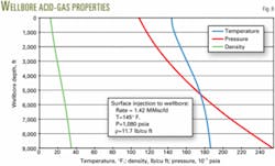
The temperature of the blended acid gas initially cools after entering the wellbore because the temperature of the earth in the upper portion of the wellbore is cooler than the acid gas. This cooling is offset by heat input at the wellsite heater.
Once the blended acid gas is a few thousand feet below the surface, the temperature in the rock layers through which it is passing becomes more favorable, gradually increasing to the bottomhole temperature of 140° F.
The pressure of the blended acid gas increases continuously in the wellbore as the depth increases due to increasing hydrostatic head. Autocompression of the acid gas as the depth and static head increases down the wellbore causes a slight increase in the acid-gas temperature above the formation temperature (Fig. 8).
The blended acid-gas density in the tubing string changes with depth because pressure and temperature change with depth (Fig. 8). The surface wellhead injection pressure is principally a function of the average acid-gas density in the wellbore, assuming constant flow rate. If the average density increases, the surface injection pressure decreases and vice versa.
Surface injection temperature is the most important determinant of average wellbore acid-gas density and therefore surface injection pressure. Changing the outlet temperature of the wellsite heater will change the surface injection pressure and the associated pressure drop across the PCV.
Mississippian limestone reservoir
The Mississippian limestone is the productive formation for the Lisbon oil and gas reservoir. Perforations in injection Well B-624 are several hundred feet structurally downdip to those in the nearest producing wells.
Well B-624 is 4,000 ft from the next nearest Mississippian wellbore, which is temporarily abandoned Well A-713.
Well B-624 is 7,200 ft from the nearest producing well B-614-A.
Static reservoir pressure was measured as 2,500 psig at a depth of 8,800 ft on May 20, 2002, after a reasonable shut-in period.
The static reservoir temperature was 140° F. at 8,800 ft at the same time.
A pressure fall-off test conducted at the same time using Lisbon produced water (specific gravity 1.05) indicated the B-624 had a 2-md permeability.
The Mississippian reservoir is a 500-ft thick limestone regionally extensive at a depth of about 9,000 ft below surface.
The thick, fractured limestone has dozens of dolomitic vuggy intervals that enhance permeability and therefore the well's capability to take water or high-pressure acid gas.
Operators injected more than 50 million bbl of salt water into Well B-624 from 1965 to May 2003.
Disposing of the blended acid gas into Well B-624 is ideal because it is going into the essentially infinite sour water aquifer underlying the oil and gas accumulation from which it came from.


