Coordinated optimization, new well design reduce wellbore stability problems in Valhall field
Teamwork and field-specific operational practices adopted for the Valhall field, Norwegian North Sea, helped limit wellbore instability, lost circulation, and stuck-pipe problems.
Knowledge-management tools and processes were used to refine these procedures over 24 months, implementing a new well design and 113/4-in. liner surge-reduction techniques. As a result, dry hole days/1,000 ft improved by about 40% in wells drilled at an inclination of 50º through the overburden. The primary goal of setting 95/8-in. casing in the reservoir was achieved in six wells, whereas previously failure to set casing was common.
Subsidence
The Valhall field, in Block 2/8 of the Norwegian sector of the North Sea, is one of the most mature fields in the Norwegian Continental Shelf, with more than 150 wells drilled to date. Over time, depletion of the reservoir, water and waste injection, and the presence of a gas cloud have together weakened the faulted overburden. Subsidence has occurred by up to 4 m at the seabed and 8-10 m at the top of the reservoir.
Extended reach drilling (ERD) of the Valhall wells has become increasingly difficult over time because subsidence has narrowed the window between the fracture gradient and collapse pressure in the overburden.
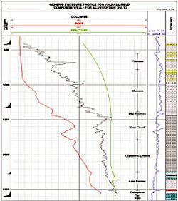
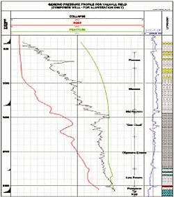
Fig. 1 shows the generic pressure profile of the Valhall field; the graph demonstrates the abnormal pore pressure development as well as the narrow window between the collapse pressure and the fracture gradient in the overburden interval between 1,400 m TVD and the top reservoir.
Since 1994, an increasing number of ERD wells have failed to set the 95/8-in. casing shoe in the top reservoir. Stuck pipe, stuck liners, fluid losses, and technical sidetracks have frequently occurred below the 133/8-in. casing, in the 121/4-in. section through the overburden. Repeatedly, loss of a slot and lost or delayed production have resulted in high costs for the operating company.
Wellbore stability service
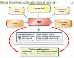
The operator, in cooperation with the service company, implemented a new approach to solve the wellbore stability problems. The approach involved creation of a multidisciplinary team with a drilling optimization engineer as the focal point (Fig. 2).
During the planning phase of a new well, this engineer's main objectives were to plan the hydraulic regime including a targeted equivalent circulating density (ECD) for the well and develop the best possible drilling procedures for the main wellbore and offsets.
During the implementation phase, requirements included wellsite awareness training, real-time decision making, data acquisition, monitoring of hole cleaning, and the correct application of drilling procedures. The knowledge captured during the well construction was stored in a proprietary knowledge-management database and the lessons learned were relayed back to the drilling teams to close the loop.
Best drilling practices
Evaluation of offset wells revealed that incorrect drilling practices can easily cause an increase in ECD of up to 0.4 ppg. In some areas of the Valhall overburden, there is a narrow window between collapse pressure and fracture gradient of less than 0.5 ppg. Therefore, pressure changes arising from drilling practices can make the difference between success and failure. An ECD target of 15 ppg was established for all the procedures and practices.
Using the results and knowledge gained through the offset well evaluation, team members developed a drilling school and "A Guide to Drilling on Valhall from a Wellbore Stability Perspective" to communicate the correct drilling procedures to the drilling team.
The ECD finger-printing process has been a valuable tool in the development and validation of the procedures, identifying the impact of different operational procedures on the ECD. In this process, different parameters and operations (rpm, flow rate, tripping speed, temperature, etc.) are varied in a controlled environment while changes in downhole pressure are recorded.
Hole cleaning
Theoretical torque and drag plots were provided prior to drilling and running casing. During operations, these plots were updated continuously to assess hole conditions accurately. In addition, real-time ECD plots, volume plots, and the pickup and slack weights at each connection were used to validate downhole conditions.
New well design
In order to drill the overburden successfully and consistently, the drilling team worked on four fundamental design aspects:
1. Minimize instability problems by adopting the 113/4-in. liner as part of the primary well design rather than as a contingency measure. The track record for the Valhall field suggested that once problems developed, it was too late to run a contingency liner in the overburden.
2. Define the depth window for setting the 113/4-in. liner after a review with the subsurface team.
Minimum setting depth: Intra Oligocene marker (1,930 m TVD RKB) to ensure that the gas cloud and Miocene faults are cased off.
Maximum setting depth: 60 m TVD about Intra Late Eocene marker (2,230 m TVD RKB), which would be above the main hard limestone stringers, thus ensuring the drill-ahead BHA is outside the 113/4-in. shoe prior to drilling the stringers.
3. Minimize surge pressures to the formation by redesigning the 113/4-in. liner, running equipment and procedures to reduce flow restriction and, thereby, surge.
4. Adopt a cementing method that will not damage the formation and prevent drilling ahead; use cementing tools that do not jeopardize the new liner's surge-reduction capabilities.
Surge-reduction design
Several modifications were made to the liner equipment to reduce surge and still provide effective cementing from the rig floor to the liner shoe (Fig. 3).
The design includes the use of a flow diverter tool positioned one stand of drill pipe behind the running tool of the liner hanger.
The tool has an internal sleeve that, when open, provides a flow area of 9.9 sq in.
This tool is considered the most important factor in limiting surge when running the 113/4-in. liner.
The second most important equipment-related factor in reducing surge is predrilling 20 holes (24-mm diameter) into a joint of the 113/4-in. liner at 60º phasing.
These predrilled holes above the liner shoe allow fluid to take the path of least resistance when being displaced either through the liner and through the flow diverter tool or around the shoe and up the annulus of the 113/4-in. liner.
Surge during cementing
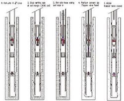
Attempting to squeeze cement through the liner shoe will almost certainly fracture the formation in overcoming the packoffs around the 113/4-in. liner x 121/4-in. hole section. With perforations already drilled in the liner, a squeeze cement job with an inner string can be performed immediately after the liner tool is pulled out, eliminating the need to run perforating guns (Fig. 4).
The squeeze cementing procedure was designed to prevent formation fracturing. Predrilled holes in the 113/4-in. liner eliminate the need to run perforating guns (Fig. 4).
Success rate
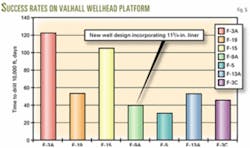
There were dramatic improvements in well delivery on Valhall crestal wells following the adoption of the new well design in 2000. However, using the 113/4-in. liner potentially increases the time to drill the overburden by 5-7 days.
Fig. 5 shows the number of days required to drill 10,000 ft from the Valhall wellhead platform and Valhall drilling platform since 2000.
Despite the extra time required to set the 113/4-in. line, the results demonstrate an improvement in drilling performance.
More importantly, all wells with the new well design have successfully installed the 95/8-in. liner in the reservoir and have been completed as producers.
Acknowledgment
The authors thank the management of BP Norway, their Valhall partners Amerada Hess Corp., Enterprise Oil PLC, Total SA, and Baker Hughes Inc. for permission to publish this article.
Based on a presentation to the SPE Latin American and Caribbean Petroleum Engineering Conference, Port-of-Spain, Trinidad, Apr. 27-30, 2003.
The authors
Richard Smith ([email protected]) is the Valhall drilling team leader at BP Norge AS, Stavanger. He has also served as drilling superintendent for BP in Aberdeen. Smith holds a BSc from the University of Southampton and an MEng from Heriot-Watt University, Edinburgh. He is a member of SPE.
Mike Simpson ([email protected]) is the senior drilling engineer on the Valhall injection platform in Norway for BP. Simpson has been seconded to BP from Baker Hughes since 1996. He holds a BSc (Hon.) in combined science (1987) from the University of Sunderland in England.
Armin K. Wicker (armin. [email protected]) is district manager for Oman & Iraq for the Hughes Christensen division of Baker Hughes Inc., based in Muscat, Oman. Earlier, he served as the Baker Hughes Oasis operations manager for the North Sea. He joined Baker Hughes after obtaining his MS (1994) in drilling, production, and reservoir engineering from the University of Clausthal, Germany. Wicker is a member of SPE.
