Process optimizes fracs in Paddy reservoir
BP PLC adopted a process that incorporates enhanced reservoir characterization for optimizing well completions in the Paddy reservoir of northeast British Columbia. Previous attempts to fracture-stimulate wells in the field had proven difficult because of the inability to generate sufficient fracture width necessary for proppant placement.
BP used Schlumberger Inc.'s PowerSTIM reservoir characterization and production optimization process to design hydraulic fracture treatments on two wells in the Paddy reservoir. The treatments resulted in successful proppant placement at designed levels.
Based on a presentation to the Petroleum Society's Canadian International Petroleum Conference, Calgary, June 11-13, 2002.
By comparison, a large majority of previous fracture treatments on 10 surrounding wells had premature screenouts or far less proppant placement than in the two BP wells. Consequently, most of these earlier wells were under-stimulated and therefore unable to produce at their potential.
Paddy formation
The Paddy member consists of the upper portion of the Peace River formation of northwest Alberta and northeast British Columbia.
Paddy is a fluvial sand of thinly bedded sandstones and shales with occasional thin coals. Pay quality varies from well to well.
Reservoir pressure in the Paddy study area is about 1,523 psi (10,500 kPa), with rock porosity ranging from 9 to 14% and permeability from 1 to 15 md. Net pay ranges from 13 to 39 ft.
BP and other operators have considered the Paddy formation to be water-sensitive.
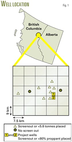
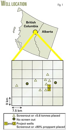
Hydraulic fracture treatments in the Paddy, heretofore, have most often yielded substandard results because of the inability to place sufficient proppant in the formation. Eighty percent of the fracture treatments in the study area had experienced premature screenouts or placed less than 12,320 lb of proppant into the formation (Fig. 1).
As a result, most wells were stimulated at levels far less than what was needed to maximize production.
Prior treatments
A preliminary review of previous fracture treatments identified reasons for past failures. Data from the treatments showed the presence of abnormally high treatment pressures in many instances, and BP's recent work lent insight into the causes for the high pressure.
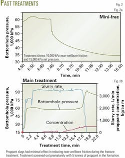
Bottomhole pressure (BHP) data analysis from a mini-frac treatment disclosed the existence of excessive near-wellbore friction and respective net pressures of 1,450 and 2,175 psi during treatment (Fig. 2a).
The presence of excessive near-wellbore friction and net treating pressures accounted for the high treating pressures observed on past treatments. It also gives evidence that the treatments had generated insufficient fracture width to enable successful proppant placement; hence, the reason for premature screenouts on past treatments.
Proppant slugs pumped during a fracture treatment attempted to reduce the near-wellbore friction to a more manageable level. This, however, had only a minimal effect and the treatment screened out after only placing 11,000 lb of proppant (Fig. 2b).
The study area is in a tectonically stressed environment that results in abnormal rock stress that possibly causes excessive near-wellbore friction and the net pressures recorded during the treatments. This area lies within the Rocky Mountains foothills, east of the range's main disturbed belt. The area has minor structural disturbances and lateral stress anisotropy (stress contrast between rocks).
Indirect evidence that supported characterizing the Paddy reservoir as tectonically stressed included:
- Dipole shear-sonic imager (DSI) log data.
- The fact that adequate calibration of the mechanical properties log from data acquired during a mini-frac required manipulation of the tectonic component in the equation for calculating minimum horizontal stress.
Because the problems with past hydraulic fracture treatments resulted from excessive near-wellbore friction and net pressures in a highly tectonically stressed environment, Schlumberger recommended to BP that future fracture treatments require an engineered solution to ensure successful proppant placement. BP accepted this recommendation.
Design team
BP and Schlumberger formed a multidiscipline team that used the PowerSTIM process to provide complete reservoir characterization, engage in detailed evaluation of past fracture treatments, and develop a solution for successfully placing future treatments.
Key components of the process were:
- The team made decisions on the basis of thorough analysis of the relevant dataset, as opposed to "quick look" data analysis.
- The team included local experts from the operator and Schlumberger, in addition to pertinent specialists and management personnel from other parts of the companies.
- The team consistently adhered to a decision-making process supported by dataset analysis.
Solution development
A number of geologic and engineering factors can lead to near-wellbore problems, among them:
- Multiple fractures.
- Convoluted or tortuous pathway.
- Insufficient or misaligned perforations.
- Induced rock pinching.
- A micro-annulus.
To design a solution, one has to sufficiently address the specific conditions and their severity in a given reservoir. Analysis suggested that completing the wells with oriented perforating technology would likely prove cost-effective for enhancing fracture treatment performance.
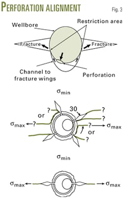
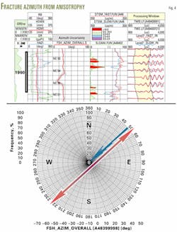
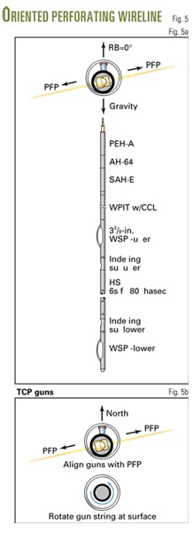
Oriented perforating requires reservoir measurements and employs perforating technology to align the perforations with the preferred fracture plane (PFP) in the reservoir rock (Figs. 3 and 4). The PFP is the path of least resistance, resulting from differences in direction and magnitude of formation stresses.
Alignment with the PFP optimizes the number of hole openings directly toward the fracture. This increases the energy that can be focused in the proper direction and minimizes near-wellbore complexities.
Oriented perforating can be done with either wireline or tubing-conveyed perforating (TCP) methods (Fig. 5).
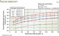
Another major factor involved finding a way to obtain a highly conductive fracture, as opposed to significantly increasing fracture length (Fig. 6). This is a priority in reservoirs with at least moderately high in situ permeability, such as the Paddy, which has measured permeablities of 5-15 md.
Achieving highly conductive fractures with a sufficient fracture width can be a challenge where near-wellbore effects exist.
All of these considerations pointed in the direction of designing a tip-screenout fracture stimulation treatment, which achieves high fracture conductivity without having to pump excessive proppant concentrations.
The treatment involves first pumping the fluid pad for creating the fracture length and then pumping the proppant to the fracture tip. In this treatment, proppant continually is added so that the fracture balloons1 and widens.
Measurement of net pressure gain during pumping, once proppant has reached the fracture tip, affords a qualitative indication of tip screenout.
Accurate BHP measurements and a mini-frac to obtain fluid property values are essential for proper design, execution, and evaluation of a tip screenout treatment.2-5 With this information, numerical modeling and fracture design can proceed with the use of appropriate software.
With a model, one can assess tip screenout events and evaluate fracture treatments with pressure matching simulations.
Based on thorough analysis of the dataset assembled and assessment of the pertinent technological options, the team recommended the following re-engineered completion solution:
- Run a dipole shear sonic imager tool to obtain stress anisotropy, fracture azimuth and mechanical rock properties.
- Use oriented perforating to provide a single initiation point into the preferred fracture plane.
- Perform a mini-frac treatment to obtain fracturing fluid properties and measure near-wellbore friction.
- Run real-time BHP recorders for accurate BHP measurement during the mini-frac and tip-screenout fracture treatments.
- Employ a water-based crosslinked fluid in the treatment for additional viscosity.
Initial well results
Well No. 1 was completed via the reengineered process.
Before setting casing, a dipole shear sonic image log was run to obtain mechanical properties, stress anisotropy and the preferred fracture azimuth.
Log data interpretation revealed a preferred fracture azimuth of 39° (NE-SW). Oriented perforating was executed from 6,319-45 ft with TCP tools.
The procedure involved pumping a 7,924 gal mini-frac at 22 bbl/min through 3.5-in. tubing with a fluid system comprised of a water-based 30 lb/1,000 gal borate crosslinked gel.
A gauge recorded the instantaneous shut-in pressure (ISIP) when the treatment was flush to the top perforations. Monitoring of the pressure decline then allowed the operators to determine the closure pressure.
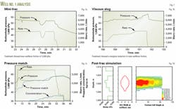
During the treatment, a BHP gauge enabled real-time BHP measurement. When the treatment was shut down, the team calculated the near-wellbore friction at 725 psi by measuring the difference between BHP just before shutdown and the ISIP (Fig. 7a).
These results showed a 50% reduction in near-wellbore friction, compared with prior area treatments. Pressure decline analysis revealed a closure pressure of 5,076 psi, resulting in a net pressure of 1,595 psi.
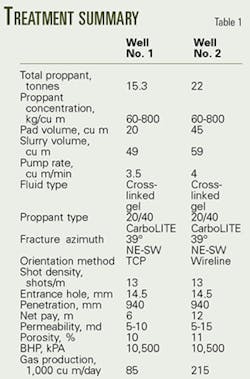
The team designed a tip-screenout fracture treatment, based on the mechanical properties disclosed by the logs and fluid properties determined from the mini-frac analysis (Table 1).
The treatment successfully placed 33,660 lb of proppant into the formation (Fig. 7b).
The tip screenout was shown by the data analysis indicating an 890-psi net pressure gain during the treatment after the proppant began to pack off in the fracture. The team evaluated the treatment by pressure matching computer simulation results to pressures observed during the treatment.
The pressure match results suggest that the treatment resulted in a fracture half-length of about 295 ft, with average proppant concentration of 1 lb/sq ft (Figs. 7c and 7d).
The well tested at an initial rate of 3.01 MMcfd after the treatment.
Second well results
Well No. 2 included the same reengineered completion process as in the first well.
Data interpreted from the dipole shear sonic image log that was run showed the preferred fracture azimuth to be 50° (NE-SW).
Oriented perforating was done; however, this time via wireline from 6,408 to 6,454 ft.
A 6,604-gal mini-frac treatment followed, with the pumping rate, tubing diameter and fluid system identical to those in the mini-frac performed on Well No. 1.
Treatment displacement to the top perforations, pump shutdown, recording of ISIP, and monitoring of pressure decline through treatment closure all proceeded on the same basis as on Well No. 1, with real-time BHP measurements likewise obtained throughout the treatment from a BHP gauge.
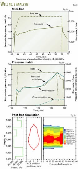
The team calculated a near-wellbore friction of 609 psi at shutdown, applying the same method as on the first well (Fig. 8a).
The results disclosed a greater than 50% decline in near-wellbore friction, compared with past nearby treatments.
Pressure decline analysis revealed a closure pressure of 4,757 psi, resulting in a net pressure of 1,668 psi.
The team designed a tip-screenout fracture treatment based on similar analysis to Well No. 1 (Table 1). The treatment successfully placed 48,400 lb of proppant into the formation (Fig. 8b).
The tip screenout was shown by the data analysis indicating a 1,740-psi net pressure gain during the treatment after the proppant began to pack off in the fracture.
Results from matching the computer simulation with actual pressures suggest that the treatment resulted in a fracture half-length of about 210 ft, with average proppant concentration of 2 lb/sq ft (Fig. 8c).
The well tested at an initial rate of 7.63 MMscfd after the treatment.
Design benefits
Interpretation of the results emerging from the reengineered completions designed through the process for the two wells in the Paddy reservoir yielded the following key benefits:
- High near-wellbore friction and net pressures encountered during fracture treatments give evidence of a tectonically stressed environment.
- Combined use of oriented perforating and crosslinked gel fluid significantly reduced near-wellbore friction, allowing greater placement and higher concentrations of proppant for enhanced conductivity and production response.
- Use of water-based fracturing fluids proved less damaging than originally feared, as shown by production data.
As a final observation, teamwork was essential in the creation of a completion solution for the Paddy reservoir.
References
1. Elbel, J., and Britt, L., Fracture Treatment Design; Reservoir Stimulation, Third Edition, Wiley Co., NY 2000.
2. Thompson, J.W., and Church, D., "Design, Execution, and Evaluation of Minifracs in the Field: A Practical Approach and Case Study," Paper No. SPE 26034, Western Regional Meeting and Exhibition, Anchorage, May 26-28, 1993.
3. Nolte, K.G., "Determination of Fracture Parameters From Fracturing Pressure Decline," Paper No. SPE 8341, SPE Annual Technical Conference and Exhibition, Las Vegas, Sept. 23-26, 1979.
4. Nolte, K.G., "Fracturing Pressure Analysis: Deviations From Ideal Assumptions, Paper No. SPE 20704, SPE Annual Technical Conference and Exhibition, New Orleans, Sept. 23-26, 1991.
5. Castillo, J.L., "Modified Fracture Pressure Decline Analysis Including Pressure-Dependent Leakoff," Paper No. SPE 16417, SPE/DOE Low Permeability Reservoirs Symposium, Denver, May 18-19, 1987.
The authors
John W. Thompson is a senior DESC (design and evaluation services for clients) engineer with Schlumberger. He currently is assigned to BP Canada Energy Co. and has held various positions in marketing, sales, and operations for Schlumberger. Thompson has a BS in petroleum engineering from Texas A&M University and a BBA in marketing and management from Southwest Texas State University.
Joseph A. Khoury is the Schlumberger reservoir evaluation DESC engineer for BP Canada Energy Co. He has held various operations, marketing, and client support positions for open and cased-hole log evaluation with Schlumberger. Khoury has an MS in geological engineering from ENTP, Lyon, France.
Sheila A. Reader is senior operations engineer for the Noel area in British Columbia with BP Canada Energy Co. She previously has worked as a reserves analyst and reservoir engineer. Reader has a BS in geological engineering from the University of British Columbia.
Bryan J. Ireland is an advisor in the area of clastic sedimentary geology with BP Canada Energy Co., Calgary, where he is currently working in tight formation gas. He has worked as a clastic petrologist and sedimentologist and has been involved in a variety of exploration and development assignments. Ireland received a BS in geology from the University of Southampton, UK and a PhD in clay mineralogy from the University of Sheffield, UK.
