Deepwater gas development off Egypt overcomes challenges
Development designs for deepwater gas fields, in the West Delta Deep Marine (WDDM) concession off Alexandria, Egypt, have overcome various flow assurance and operability challenges because of the long step-outs, water depths, and high production and availability requirements, according to Clive Kitson of BG Group, Reading, UK, and Tom Choate of Intec Engineering, Houston, in an account of the project provided to the Oil & Gas Journal.
They said that the industry at large also faces these issues as it develops other long step-out deepwater fields.
The operator of the WDDM concession is Burullus Gas Co., a joint venture of BG-Egypt SA (25%), Edison International SPA (25%), and Egyptian General Petroleum Co. (EGPC; 50%). Since 1997, BG Egypt has drilled 16 exploration and appraisal wells, with 100% success rate in the WDDM concession.
Kitson and Choate said that an integrated system design for such projects must provide the requisite levels of performance and reliability. A design's objective should achieve maximum profitability within the bounds of technical, governmental, environmental, and social constraints.
From a flow assurance and operability perspective, Kitson and Choate believe that the main deepwater and long step-out challenges are to:
- Prevent production disruptions due to hydrate formation.
- Control the corrosion rate of large-diameter, long life, pipelines.
- Optimize system pressure to conserve reservoir energy as well as manage large flow-rate swings that result in liquid fluctuations.
At these step-outs and water depths, there are also significant challenges for the subsea control system to provide a reliable means for monitoring and controlling production.
WDDM projects
The first fields to produce in the WDDM concession will be Scarab and Saffron. The fields are currently being commissioned and BG expects first gas in the first quarter of 2003. The gas will supply Egypt's domestic market.
Next on the schedule are the Simian and Sienna fields that will tie into the Scarab-Saffron development. These fields will be the first in the world to deliver deepwater gas to shore for LNG production.
At water depths of 1,000 m and greater and more than 120 km from shore, these fields also will have one of the world's longest step-out (the distance between the wells and processing facilities), surpassing the record set in 1995 by Shell Exploration & Production Co.'s Mensa gas field in the Gulf of Mexico, according to Kitson and Choate.
The schedule calls for completing the Simian and Sienna offshore and onshore facilities by third quarter 2005.
The Sapphire field development is scheduled to follow in 2006 and also tie into Scarab-Saffron fields. The field is intended to provide gas to the second LNG train.
Upon completion, BG expects the three developments to produce almost 2 bcfd from the WDDM concession.
In April 2001, BG Egypt signed an agreement to develop an Egyptian LNG (ELNG) export project and became the only upstream company in Egypt with an export agreement from within a concession area.
The partners in ELNG issued Bechtel Corp. the notice to proceed with the engineering, procurement, and construction (EPC) of a $900-million downstream plant for the first LNG train in September 2002. Currently being tendered is the engineering, procurement, installation, and commissioning (EPIC) for the Simian-Sienna offshore upstream facilities. Sapphire is in the presanction phase.
In October 2002, BG and its partners announced the sale-purchase agreement of the total LNG output of first train to Gaz de France. Under the agreement, ELNG will deliver 3.6 million tonnes/year of LNG for 20 years. The agreement is in line with BG's strategy for supplying the entire gas chain from source to end user, according to Kitson and Choate.
They said ELNG is one of the fastest developing LNG export plants in the industry and Egypt will undoubtedly derive substantial economic benefit as it becomes a significant LNG exporter.
BG and its deepwater design contractor, Intec Engineering, a member of the Heerema Group, reviewed various concepts for long step-out gas systems and found that the most effective design, in terms of installed cost, safety, environmental impact, and operational efficiency was a design that eliminates surface infrastructure such as gas processing platforms or floating production units.
Kitson and Choate indicate that another design consideration was that the overall LNG system requires a production availability of 93%; therefore, the Simian-Sienna production system includes proven technology and available intervention capabilities in order to deliver a corresponding upstream availability of 97%.
Control platform
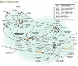
To avoid excessive umbilical lengths, the Simian-Sienna development calls for an unmanned shallow water platform 56 km from shore. The platform will supply the hydraulic and electrical power for operating the fields (Fig. 1).
For this purpose, previous projects have involved floating units at the deepwater field. Burullus, however, decided to install a platform in less than 60 m of water. The shallow-water platform concept has better load-bearing capacity than a control buoy and is less expensive than either a buoy or floating unit, according to Kitson and Choate.
The platform also can serve as a hub for the future Sapphire and other field developments in the area.
Operators will control the unmanned platform from shore via a fiber-optic cable with a back-up satellite link. The shore facilities also will supply the electrical power.
Hydrates, corrosion
The projects will use monoethylene glycol (MEG) for hydrate prevention. MEG is more cost effective than the alternative methanol systems because it can be recycled in the onshore processing plant, Kitson and Choate said. They added that in part, MEG also serves as a corrosion inhibitor.
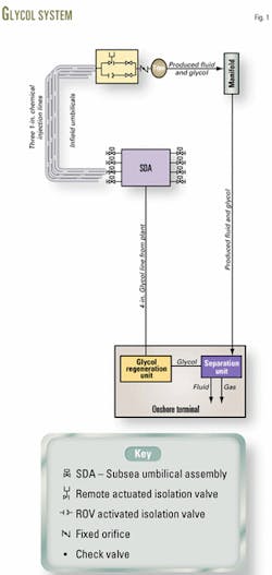
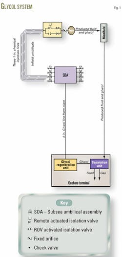
A 4-in. pipeline will transport the MEG from shore to an infield subsea distribution assembly (SDA) connected to the wells with umbilicals (Fig. 2). Kitson and Choate explained that this distribution system eliminates the prohibitive expense of discrete long-distance supply lines from shore to each well.
At the wellhead, the operations call for continuously injecting MEG downstream from the production chokes. A control unit will supply a constant rate to meet the requirements of the maximum expected gas flow, water production (conservatively estimated), and the lowest expected temperature in the subsea system, and the maximum potential flowline shut-in pressure.
They said that the system is designed so that the MEG rate supplied to each well is little affected by the actual pressure at the point of injection. An efficient onshore MEG regeneration allows for the conservative approach of continuously oversuppling MEG to the wells.
Each MEG control unit has two independent and independently isolatable flow-control valves. The simplest, and the one used initially, will be an orifice that is sized for modest water production, an amount BG expects not to be exceeded by most wells.
The second valve is adjustable and can handle 10 times greater MEG rates than the orifice. These valves will be used when or if water production rates increase, according to Kitson and Choate.
The plan is that a remotely operated vehicle (ROV) will retrieve the control units if they require maintenance.
In addition to MEG, the projects calls for using methanol to inhibit hydrate formation during start-up and until warm flowing temperatures are reached at the exiting choke. The methanol will inhibit wellhead areas on shutdown, help remediate hydrate plugs, and purge vent lines after use. Methanol transport is via the main umbilical to the SDA and then via infield umbilicals to the trees and manifolds.
Kitson and Choate said that malfunction of the MEG injection system could result in hydrate formation somewhere in the production system. To avoid downtime that would be required to depressurize and melt a hydrate plug, once formed, the operators will use a production system simulator (PSS) to identify flow conditions that indicate the on-set of hydrate formation, said Kitson and Choate.
They explained that useful indications of hydrate formation include an increase in wellhead or other system pressures, large pressure fluctuations, or a decrease in gas flow. If the operator detects hydrate formation, the remediation strategy is to flow methanol through the hydrate in an attempt to melt it in situ without depressurization.
The strategy is to depressurize only if necessary, according to Kitson and Choate. They add that because of the expense involved in depressurizing the systems to shore, 4-in. bore lines installed between the trees, SDA, and manifolds will allow venting of the lines into the 24 and 36-in. export pipelines.
In this case, they say the procedure is to inject methanol at available points closest to fluid entry into the vent lines. Following depressurization, the vent lines will be purged and left filled with methanol.
The operations include continuous injection of a liquid-phase corrosion inhibitor along with the MEG for corrosion inhibition. Kitson and Choate explained that the system does not require a gas-phase inhibitor because the liquid phase carries sufficient MEG.
They said that the corrosion inhibitor and pipeline corrosion allowance fully protect the flowlines and pipelines, thereby eliminating the need for costly intelligent pig inspections. They added that a continuous onshore monitoring program for MEG, corrosion inhibitor, and corrosion products coming from the pipelines will ensure effective corrosion management.
System operations
BG expects each WDDM field to have a nominal production rate of 600-MMscfd.
The production system in each field will typically have 7-in. tubing downhole, 10-in. flowlines, and 20-in. export lines that connect to a pipeline-end manifold (PLEM) in shallower water. From the PLEM, the combined production from all of the fields of up to 2 bcfd will enter parallel 24 and 36-in. pipelines to shore.
Kitson and Choate said that operations will normally require a production between peak and half that rate, and they added that occasionally rates may decrease to one quarter peak from each field due to the phasing of the different fields and both pipelines may at times operate at half peak.
The system tightly integrates the pipeline hydraulic design (diameter) with the design for operations (flow assurance). Kitson and Choate said that this allows for conserving reservoir pressure, accommodating liquid holdups that can occur at low rates, and optimizing cost.
Early in the field's life, Kitson and Choate said that the operations will require individual wells to be choked back to the required production rate and to keep the pipelines at 88 barg (1,276 psig). As reservoir energy depletes, the plans are to add onshore compression and reduce the operating pipeline pressure to about 25 barg.
Kitson and Choate said that liquid hold-up will increase markedly as the production rate in the large-diameter pipelines decreases. At these lower rates, operators will carefully control ramp-ups from the turndown conditions to keep liquid-delivery rates within the liquid-handling capacity of the onshore receiving and processing equipment.
They said that, to avoid unnecessary production disruptions, the operations require a sophisticated understanding of system hydraulic behavior. The results of dynamic multiphase simulation studies demonstrate that, from about 50% of peak production, these systems have good flexibility and turndown and ramp-up can be accomplished in a few hours.
They said that at 25% production or less, however, operators will have to control carefully the ramp-up by using long ramp-up durations over a number of days to avoid excessive liquid hold-up.
Another important aspect of system management is the control of the total system MEG volumes. During high-production-rate periods, the piplelines will have relatively little liquid, but during low-production periods, the long and large-diameter inclined pipelines will have high liquid holdup, according to Kitson and Choate.
They said that at all times the liquid in the system will be mostly a mixture of water and MEG, with the MEG holdup between high and low rates of about 25,000 bbl or more. The MEG will reside in onshore storage during high-rate operations and will reside in the pipelines during low-rate operations.
Onshore storage must accommodate the MEG from the pipeline when the system goes from low to high-rate operations, they said.
Production monitoring
Onshore operators will use state-of-the-art production monitoring in several forms to obtain key subsea system data. Kitson and Choate said that the instruments include:
- Single-phase downhole venturi meters for direct measurement of reservoir production.
- An inference metering system for obtaining pressure and temperature measurements downhole, at the trees, and in the flowlines. The data will be used to predict gas, condensate, and water production rates from each well.
- Dual in-stream sand detectors mounted downstream from the production chokes for monitoring produced sand.
- An onshore dynamic production system simulator (PSS) for monitoring flowing conditions (such as pressures and production rates), predicting future response to system control actions (such as liquid surge resulting from a change in production rate), and alerting the operator of current or future problems.
The PSS may be a major aid in monitoring hydrate indications and planning and executing production ramp-up operations that would otherwise be very difficult.
In addition to these instruments, the design allows the subsea control system to be retrofitted later with subsea multiphase wet-gas meters in the flowline jumpers, if necessary.
Long distance controls
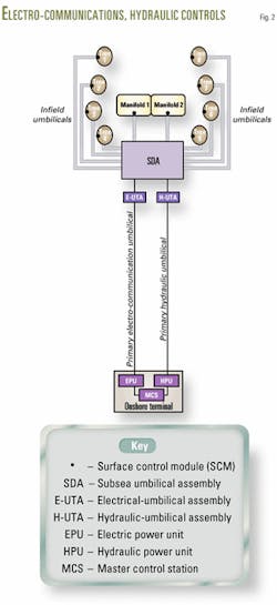
Kitson and Choate said operators will control well production with hydraulic, communication, and electrical power systems (Fig. 3).
The hydraulic systems' ability to actuate valves and transport hydrate and corrosion inhibition chemicals to the trees depends on both distance and depth. Increased distance also increases the losses of electrical power delivered to the subsea electronics module (SEM).
Without sufficient power, they said, the SEM cannot send valve command signals to the trees or communicate data on valve positions, flow rates, pressures, and temperatures back to the on-shore master control station (MCS). Communication signals back to the MCS are in themselves subjected to further attenuation over extended step-out distances.
They said that the design of long-distance controls, therefore, incorporates measures to increase the hydraulic, electrical power, and signal capability and to reduce the resistance in their transmission via the longer umbilicals from the MCS to the field.
They see the main challenges of the production control system as:
- Providing sufficient hydraulic power to overcome pressure losses and static head over distance and depth and to actuate the downhole and subsea valves.
- Ensuring the correct dose of chemical inhibitor (MEG and corrosion inhibitor) is delivered to the well stream.
- Providing high-voltage electrical power to the subsea electronics modules allowing for hook-up and retrieval of electronic equipment with ROV operable subsea connectors.
- Transmitting and receiving data signals, between the field and the shore, with minimum attenuation and noise.
- Manufacturing several hundreds of kilometers of corrosion resistant steel tube, with zero weld defects, and installing continuous length umbilicals to transmit hydraulic power to the field.
- Manufacturing and installing continuous length electro-communications cables capable of transmitting electrical power and data signals with minimum attenuation and noise.
Hydraulic control
The plan calls for an hydraulic power unit (HPU) to supply hydraulic power to both a low pressure (3,000 psi) and a high-pressure (7,500 psi) system.
The low-pressure system connects to directional control valves that actuate valves at the trees and in the manifold. The high-pressure system actuates the downhole safety valve.
Hydraulic systems use accumulation to achieve acceptable actuator response times. As water depth increases, pre-charge pressures increase and accumulators become less effective in delivering the required fluid amount, and thus extend the time to open each valve, according to Kitson and Choate.
They said that currently opening a large valve can take up to 2 min. Longer times are undesirable because the valve gate becomes subject to more erosion and subsequent loss of reliability.
Fluid viscosity, tube diameters, and roughness are important considerations in delivering hydraulic fluid over long distances.
Kitson and Choate said that the open-loop systems in the WDDM projects eliminate the cost of long distance hydraulic-fluid return lines by expelling used actuator fluid to the sea. For environmental reasons, this requires the systems to use water-glycol-based fluids instead of low-viscosity mineral hydraulic fluids.
The fields will have hydraulic umbilicals manufactured and installed in one continuous length. Kitson and Choate said that this avoids a loss in reliability that results from subsea connections. Currently, the WDDM umbilicals are the largest in the world and at the limit of installation vessel capabilities.
In future fields, they said, new developments in subsea pressure intensifiers will allow the high-pressure system to be run from a discrete low-pressure supply. Pressure intensifiers remove the high-pressure requirement in the HPU and also reduce the amount of fluid required in the system.
Chemical inhibition
As in the hydraulic control system, delivery pressure, viscosity, and pipe roughness determine the tube sizes required to permit a flow rate that effectively doses the well stream with hydrate and corrosion inhibitors.
Kitson and Choate said reservoir properties for remote deepwater fields are less well known and never fully characterized before production because of the high exploration costs. Consequently, they said, this lack of knowledge compromises chemical injection-fluid selection because the chemical properties required for the corrosion and scale inhibitors are unknown until after the project has selected the hydraulic jumper and umbilical materials.
Electrical power
Longer step-outs need higher voltages to overcome losses in the umbilical cables. Typical systems use AC power at 400 v and 60 hz.
As voltage increases, capacitive losses within the umbilical also increase. Kitson and Choate said that this adversely affects the power factor leading to design issues within the electrical power unit (EPU).
Typical voltages for a 100-km step-out umbilical are 900 v at the shoreline supply and about 250 v at the deepwater umbilical termination assembly.
An increase in the amount of copper in the power cables can accommodate the longer distances and higher power load required by many of the wells. They said that the limit is the cable size that can be manufactured in one piece on a supplier's carousel with its size and weight constraints
Currently, they said, available wet-mateable power connectors only are rated and certified for 1 kv. For these connectors, studies show that the voltage drop and cable cross-section reach their practical limit at about 135 km.
Kitson and Choate said that the only other option is to use large and heavy connectors or subsea transformers rated to 3.3-kv voltage or greater.
Signals
For data transmission, the projects are using electrical copper-based with serial interfaces, at modest data rates, to provide for future long-distance tie-ins.
To improve the recovery from a reservoir, Kitson and Choate said, engineers require greater detail and accuracy from the sensors detecting the physical well-stream properties (temperature, pressure, multiphase flow, sand production, etc.). They said that this requires the control system to transmit more data to the MCS.
Fiber optics that carries higher data rates, up to 200 million bits/sec, would improve control system communications. They added, however, that a fully qualified subsea fiber-optic system is not yet available that can manage the current subsea unidirectional technology (one signal carrier in and one out) and also connect a number of subsea control modules to a single umbilical core (multidropping).
They said that development of wet-mateable fiber-optic connectors is also at an early stage and that the project needs to take these risks into account for specifying the numerous and unavoidable subsea connections required in any fiber-optic control system.
Hydraulic umbilical
Thermoplastic umbilicals are established technology, but the expansion characteristics of the material change over time, thereby reducing the stored fluid volume, according to Kitson and Choate.
They said that one needs to consider this performance loss when sizing accumulation because, when the umbilical is new, the charge up and emergency shutdown (ESD) times are longer than in later life.
They said that this is why most designers prefer steel-tube umbilicals for long-distance tiebacks.
Steel tubes offer consistent hydraulic performance with virtually no expansion characteristics and produce a consistent system with improved ESD response times.
The industry has seen some significant steel-tube umbilical weld and material fatigue failures, they said. Steel tube umbilicals, however, are required for deeper water, and therefore suppliers are eliminating these failures by vigorously controlling tube quality, ensuring the highest industry level of weld control, and fully testing umbilicals before shipment.
They add that the installation must limit overstressing the umbilicals to avoid any weakness becoming a potential failure point.
In recent years seawater ingress has caused problems with control-system components particularly in the SCM, according to Kitson and Choate. They said that this has occurred when the manufacturer has not fully expelled air from the system, resulting in the air pushing the poppets within hydraulic couplings off their seats, thus allowing seawater ingress because of the hydrostatic force of the water,
The umbilicals have a double-armored design. Kitson and Choate said a typical 80 km, four-tube umbilical weighs 1,500 tonnes and requires a large carousel for storage, transportation, and installation.
They said that for longer step-outs, umbilical weight and size will take manufacturers and installers to the limit of their capability to produce the continuous length that is desired to eliminate subsea connections.
Electro-communications umbilical
The industry considers copper cores, consisting of 6-sq mm screened twisted pairs, to be practical for electro-communications for 100-120 km umbilical lengths. Kitson and Choate said that in this range, installations may include repeaters to clean up the signal and retransmit.
Also under development, they said, are fiber-optics control systems for future longer step-outs. In this case, an independent 16-sq mm copper cable will supply the electrical power.
A typical electro-communication umbilical of these lengths weighs 1,000-1,500 tonnes and is within the range of suppliers and installers, said Kitson and Choate.
An alternative "comms on power" systems, in which signal and power are transmitted in the same cable, reduces umbilical diameter but was not selected because signal quality suffers and the noise becomes unacceptable for long distances.
Future requirements
Kitson and Choate said that BG and Intec Engineering overcame economic and technical challenges to achieve the high availability requirements necessary to bring deepwater gas to shore for LNG production.
Equipment and techniques, however, are at a limit, and new technology and methods will be needed for producing gas from deeper water fields at longer step-outs.
Longer distances and deeper water tend to increase system pressure drop and pipeline liquid loadings. Kitson and Choate said that for such systems, projects should consider alternate flow assurance and operability design.
As fields in WDDM come on stream, experience will be gained which will be invaluable for the future operation for fields of this type.
With a production simulator, they said, operators can anticipate the actual flow conditions and establish operating boundaries appropriate to these step-outs and pipe sizes.
Accepting operating principles, which ensure that the minimum production rate remains greater than 50% of pipeline capacity, will minimize liquid surge on ramp-up and allow increased step-out distances.
They said some new technical developments that will improve performance and allow longer step-outs in deeper water will include:
- Low-dosage hydrate inhibitors that decrease the size of inhibitor delivery systems and eliminate the glycol liquid holdups in the pipelines. Compatability with the corrosion inhibitors, however, needs to be examined
- Subsea compression that will support production as reservoirs are depleted, allow for smaller pipelines, and allow longer step-outs.
- Subsea transformers that provide higher voltage (more than 1,000 v) to be distributed to the field and then stepped down to deliver power to the control system at voltages within the range of current subsea ROV connector technology.
- Fiber optics that permit more data to be transmitted over longer distances than copper cables. Fiber optics also reduces umbilical sizes. Development also is proceeding on fiber-optic production control systems, but these will require the proving out of deepwater fiber-optic wet-mate connectors.
Statoil plans to install the first long, 160 km, step-out fiber-optic control system in the Snøhvit field in 2007. And Kitson and Choate expect all WDDM fields will have fiber-optic cables installed in their electro-communication umbilicals to be available for future extended tie-ins.


