N2 foamed spacers prevent annular pressure buildup at Marlin
Use of nitrogen-foamed spacers is a proven mitigation technique for wells with potential problems with annular pressure buildup (APB).
In late 1999, BP PLC experienced a well failure in the Marlin development in deepwater Gulf of Mexico. Within hours of starting production, the production tieback casing collapsed, causing the production tubing to fail.
An incident investigation team determined two possible causes of the failure: excessive annular pressure buildup (APB) or annular hydrate disassociation.
The failure analysis results were applied to the five remaining Marlin wells.1 When these original Marlin wells were batch drilled, several mitigation techniques were not implemented and were no longer available for consideration.
As a result, the redesign of the Marlin completions focused on vacuum-insulated tubing and fiber-optic monitoring systems as a means of controlling and observing thermal behavior.2
Marlin A-2 well failure
Early in the failure investigation, a root cause analysis attempted to identify the most likely causes of tubing ovalization.3
All of the conditions necessary for hydrate plug formation were potentially present in the annulus between the 133/8-in. casing and the 16-in. liner.
A temperature increase during production, coupled with a confined container within which dissolution might proceed, could generate enough pressure to collapse the 133/8-in. intermediate casing. That collapse could lead to a cascading point loading or collapse sequence on the production tieback and tubing.
Additionally, when the production string was cemented, the annulus between the production casing and intermediate casing was purposely sealed because of a hydrocarbon zone just below the intermediate casing. The fluids trapped in the annulus were at a relatively low temperature when the cement was set and the seal assembly at wellhead was installed.
When the well was produced, the annulus became heated from the transfer of bottomhole temperature up the well by the produced fluids.
With heat-up, the fluids in the annulus began to expand thermally and the pressure generated between the intermediate casing and the production casing collapsed that string. The collapse of the production casing immediately caused a collapse of the production tubing.
The Marlin A-2 well failure demonstrates the severe risks that APB poses to subsea well integrity and how collapse failure of outer casings can propagate inward, causing additional failures of inner casing and tubing.
The severe consequences of such failure modes demonstrate that APB mitigation should be implemented during well design.
Annular pressure buildup
APB is the pressure generated by expansion of trapped fluids as they are heated.4 In subsea completions, the primary annulus between the tubing and production casing may be the only accessible annulus; therefore, bleeding of the outer annuli may not be possible.
When a well experiences APB, a sealed annulus or temperature increase must exist. In the Marlin well, the locations of particular hydrocarbon-bearing zones effectively required that the top of cement (TOC) be high enough to risk a sealed annulus. The trapped fluid would be heated by drilling and production operations.
Deepwater wells are likely to be vulnerable to APB because of the cold seafloor temperatures at installation, in contrast to elevated production temperatures.
In the Marlin development, a review of the temperature buildups on the annuli indicated that a trapped condition would affect the casing design. Temperature modeling under various flow conditions demonstrated that the annuli would heat up to a point at which APB would predictably fail the casing. These data allowed the definition of testing criteria to design the foamed spacers that were used to mitigate the APB problems in these wells.
Mitigation strategy at Marlin
When the risk of subsea APB exists, well designers should consider appropriate mitigation in the fundamental well design. The mitigation strategy for the Marlin project consisted of using enhanced casing in conjunction with nitrified spacers and rupture disks. Multistring casing design and cement design programs were also integral parts of the well planning process.
Nitrified spacers
A nitrified spacer is placed above TOC in the annulus between the outer and inner casings to absorb the liquid-volume expansion. Over time, the nitrified spacer destabilizes and the nitrogen migrates up the annulus. When the fluids in the annulus begin to heat up due to production, the nitrogen spacer compresses to help absorb excessive pressure buildups.
The foam spacer can provide full compressibility immediately after being placed in the well and can provide adequate mud removal and remain stable for at least 72 hr.
These features help prevent nitrogen migration into the riser before the wellhead seals are set.
A series of pressure, volume, temperature (PVT) tests and well design simulations determined the minimum foam quality of nitrogen.
Foam spacer testing
Laboratory testing simulated the expected temperature and pressure conditions in the well. The test enabled reviews of fluids containing varying concentrations of nitrogen.
Temperature modeling was also performed to determine T1, the temperature that would be present immediately after cementing, and T2, the maximum temperature the annulus would see during production.
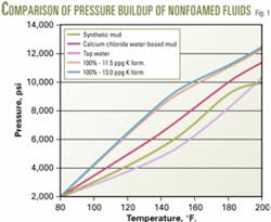
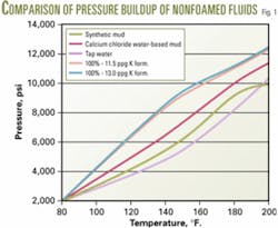
An autoclave was used to measure the pressure buildup of the fluids over the range of temperatures from T1 to T2. The initial test performed was on the synthetic oil-based mud used to drill the well.
The fluid was conditioned to 80° F. and placed in the autoclave. Pressure was applied to the sample up to 2,000 psi, which was the expected final hydrostatic pressure after the cement job. After initial pressure and temperature were applied, the temperature of the sample was increased slowly and the pressure was recorded (Fig. 1). This process was repeated with ordinary tap water as a calibration test, and finally, other fluids were tested.
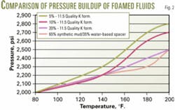
When baseline data were established, three foam qualities (5%, 10%, and 20%; Fig. 2) were placed in the test chamber.
A base-density spacer was conditioned to initial temperature conditions. The ratio of mud that would exist in the well during the primary cement job was placed in the test cell along with the remaining fluid containing the nitrified spacer. The temperature was ramped from T1 to T2, and the pressure response was recorded.
These data showed that a minimum of 5% nitrogen was required in the overall volume of the trapped annulus to prevent excessive pressure buildup. A design factor of 2 was chosen, leading to a 10% volume planned for the primary cementing operation with reference to the nitrified spacer.
Spacer, cement design
With heavier weights for the casing program and additional restrictions, the casing annuli became tighter, increasing the difficulty of placing the cement while retaining returns through the job.
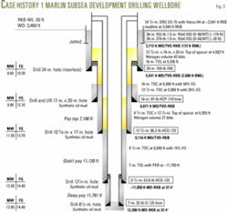
The casing design in Fig. 3 shows the position of casings and liners used in this well. The narrow clearance through the 135/8-in. casing and 16-in. liner was of particular concern due to the requirement of maintaining returns to properly place the nitrified spacer.
The spacer was designed to contain a surfactant package that would enhance mud removal and water wetting of the formation and casing. An adjustable rheology spacer was tested with varying surfactant packages and then tested to meet requirements of water-wetting.5 Afterwards, the foaming surfactants were added to the surfactant package and wettability testing was repeated.
Engineers performed other tests and the final product was a foamed spacer that would water-wet the pipe, remain stable for over 72 hr, and carry the required amount of nitrogen to be placed in the annulus.
The 72-hr stability requirement was placed on the system because, if an attempt to set the hanger seal assembly failed, several trips into the hole might be required to replace the seal assembly. The spacer and cement were designed at the same initial density. The foaming process would cover the spacer and the lead and tail cements. A constant nitrogen rate would be employed throughout the spacer and the lead cement. A rate change would then occur for the tail cement and the nitrogen would be cut off to place base cement around the shoe and into the shoe track of the casing.
The plug system was a dual-plug subsea release system. The plugs isolated the spacer and cements to help prevent contamination of the spacer system with the mud while the spacer was in the casing.
The primary reason for foaming both the spacer and the lead cement centers on displacement mechanics. At surface, the spacer will exist as a low-density system.
As the system compresses going downhole, it increases in density and viscosity. With a single nitrogen rate through the spacer and the lead portion of the cement, the system will compress as a single system and become denser as it is pumped downhole.
As the system exits the shoe, it will decompress and the densities of the system will enhance fluid displacement in the well.
Cement modeling, simulations
Cement modeling was performed before placement of all spacer and cementing fluids into the wellbore. The simulations helped the group determine the concentrations of nitrogen to be added to the fluids. Modeling also helped determine the optimum foam quality for the cement system. Foam quality below 30% helped ensure foam stability and a low-permeability final sheath.
The group identified other problems during the simulation, including a tight annulus between the drilling liner and intermediate casing.
All geometries were modeled into the simulation program to enable accurate measurement of pressure responses and help ensure that fracture gradients were not exceeded during job placement.
If there were lost returns and the spacer failed to place between the intermediate casing and surface casing, other remediation would be necessary to avoid APB-related problems. Therefore, the well design included redundant APB mitigation measures in case one measure failed.
Modeling indicated that placing the fluids as designed would require mud conditioning. After reviewing the logging and formation evaluation data, the group decided to keep the mud weight with which the hole was drilled in the open hole. Upon landing the casing, the riser mud weight was cut back.
Further circulation placed a lower mud weight in the hole before cementing. With the equivalent circulating density modeling in the cement simulation, rates were held that could ensure mud returns and allow wellbore stability through the circulation. When the lower mud weight was placed in the riser, the cement job could be carried out.
Real-time data transmission from location to the Houston office allowed comparison of the rates and equivalent pressures to the job design.
Execution, real-time operations
Real-time operations enabled personnel in Houston to review data as operations were taking place.
All rig and cementing information was transmitted and a voice line on location enabled direct communication during the job. The team successfully performed cementing operations as planned.
During the placement of the nitrified spacer and cement, modeling of fluid circulation was carried out and mud weights were dropped to ensure full returns. After the job, cement bond logs were run in conjunction with a radioactive tracer in the lead cement.
The logs indicated that the TOC was within 50 ft of design. Subsequent pressure responses during the job and final bond logging indicated that the spacer was in front of the lead cement.
Case history No. 1
BP drilled a well to recover the lost production from the failed well. The expected lithology indicated that a productive zone might be penetrated below the 16-in. drilling liner. The goal of the primary cement job on the 135/8-in. intermediate casing was to isolate this interval at approximately 7,100 ft (RKB).
The process would create a sealed annulus condition between the 135/8-in. intermediate casing, the 16-in. drilling liner, and the 20-in. conductor casing (Fig. 3).
The cement design incorporated a nitrified cementing spacer pumped just ahead of the lead cement, placing the nitrified spacer between the intermediate casing and the conductor casing. The total volume of nitrogen placed in this annulus was 43 bbl, enough to occupy 10% of the annulus volume, which was in line with the required amount plus a 100% safety factor.
The cement design software correctly predicted the job procedures required to place the cement job properly despite the threat of lost returns, and the spacer was successfully placed. Logs were run afterward to confirm the placement of the TOC and spacer.
On the same well, the next casing run, 97/8-in. production string, penetrated a productive sand just below the 135/8-in. intermediate casing that required isolation. This again would place the TOC into the previous casing. A second APB condition was predicted in the annulus between the 103/4-in. x 97/8-in. production casing and the 135/8-in. intermediate casing.
The techniques described in this article were used to design the nitrified spacers for deployment in the annulus between the production casing and intermediate casing (Fig. 3). A spacer containing 27 bbl of nitrogen was placed in the annulus, ahead of the cement job.
The well was completed and brought online. The well met production expectations and no APB problems were experienced. This well is currently one of BP's top three producing wells in the world.
Case history No. 2
BP drilled additional wells in the Marlin field that exhibited similar potential problems with APB.
In one well, the nitrified spacer was planned for placement in the annulus of the 103/4-in.. x 97/8-in. intermediate casing and 135/8-in. surface casing. Wellbore conditions caused losses during primary cementing operations, which fueled doubts about the placement of TOC and the nitrified spacer. Therefore, the team initiated an alternate plan to ensure that the proper amount of nitrogen was placed.
Before crews left the well, they pulled the seal assembly on the intermediate casing and made a wiper trip to flush the hanger. Another seal assembly was picked up and run in the well to the hanger.
Crews ran an injection test at the hanger and were able to pump in, indicating that the annulus was not sealed. A nitrified spacer of 50 bbl containing 15 bbl of nitrogen was pumped behind the seal assembly and displaced with inhibitive mud to prevent a possible hydrate formation.
Engineers assumed that because the annulus was open, a pathway existed that could allow fluid to vent at the casing shoe.
The productive interval below the intermediate casing was assumed exposed, which might allow hydrate-forming gas to migrate into the annulus and allow a trapped condition to occur at a later time.
Assuming the annulus would be trapped, the nitrogen was placed in the spacer and injected into the annulus, and the seal assembly was replaced.
The job was executed as designed, helping prevent a casing failure from APB.
General case histories
Throughout the Gulf of Mexico, many deepwater wells have been identified as having conditions that could cause a trapped annulus and allow APB to affect well integrity. Many mitigation techniques can be used to prevent APB from compromising a well design. Nitrogen-foamed cementing operations have been used for several years in the gulf, and the process is a safe and reliable technique for providing a superior primary cement job.
To date, more than 500 foamed cement operations have been successfully performed in the gulf. Use of nitrogen-foamed spacers is a proven mitigation technique for wells with potential APB problems; the spacers have been used on more than 100 jobs in the gulf. The technique has been proven with software modeling, laboratory experimentation, and field studies, and continues to be used to prevent APB.
References
1. Ellis, R.C., et al., "Marlin Failure Analysis and Redesign: Part 2, Redesign," presented to the IADC/SPE Drilling Conference, Dallas, Feb. 26-28, 2002.
2. Gosch S.W., et al., "Marlin Failure Analysis and Redesign: Part 3, VIT Completion With Real-Time," presented to the IADC/SPE Drilling Conference, Dallas, Feb. 26-28, 2002.
3. Bradford, D.W., et al., "Marlin Failure Analysis and Redesign: Part 1, Description of Failure," presented to the IADC/SPE Conference, Dallas, Feb. 26-28, 2002.
4. Moe, B., and Erpelding, P., "Annular Pressure Buildup: What Is It and What to do About It," Deepwater Technology, August 2000, p. 21.
5. Heathman, J., Wilson, J.M., and Cantrell, J.H., "Removing Subjective Judgment from Wettability Analysis Aids Displacement," presented to the IADC/SPE Drilling Conference, New Orleans, Feb. 23-25, 2000.
The authors
Richard F. Vargo Jr. (Richard.Vargo@halliburton. com) is a senior account representative working for Halliburton in BP's Houston office. He joined Halliburton in 1993 and has worked in various operations engineering capacities from 1993 to 1999 in cementing, stimulation, and logging. He has worked in Houston since 2000 for Vastar Resources Inc. then BP with their deepwater projects. Vargo holds a BS in mechanical engineering from West Virginia University and is a member of SPE and AADE.
Mike Payne ([email protected]) is a senior advisor for BP in its upstream technology group. Previously an advisor for ARCO, he has 23 years drilling experience including operations, computing, technology, and consulting. Payne holds BS and PhD degrees in mechanical engineering from Rice University, an MS in petroleum engineering from the University of Houston, and executive education from Southern Methodist University and the University of Chicago. He is chairman of the API pipe committee (SC5) and convenor of ISO SC5 WG2 and SC4 WG1.
Ronnie Faul ([email protected]) is a senior technical advisor for Halliburton's global business and technical solutions team in Houston, specializing in deepwater cementing. He joined Halliburton in 1973 and has held a variety of engineering and management positions through out South Louisiana, South Texas, and the Gulf of Mexico. He holds a BS in electrical engineering from McNeese State University, Lake Charles, La., and is a member of SPE and AADE.
John R. LeBlanc ([email protected]) is a senior drilling engineer currently working for BP GUPCO (Gulf of Suez Petroleum Company) in Cairo as a drill team supervisor. He has worked in various drilling and management positions in his 20 years in the industry in domestic and international locations. He holds a BS in petroleum engineering from the University of Southwestern Louisiana, Lafayette.
James E. Griffith ([email protected]) is assigned to Halliburton's global cementing staff as the business segment manager for cementing innovations. He is a registered petroleum engineer in Oklahoma with over 17 years of diversified petroleum engineering and field experience in production, drilling, and reservoir simulation and holds BS and MS degrees in petroleum engineering from the University of Oklahoma, Norman, and an MBA from Oklahoma City University.


