Use of high-strength line pipe can improve economics of long-distance gas lines
The recent development of X-120 high-strength steel line pipe (nominal yield strength of 120 ksi)1 enables gas producers to realize significant savings in the total cost of long-distance gas transmission pipelines, lowering the cost of supplying gas to market. These savings can be achieved from cost reductions in material, construction, compression, and integrated-project operations.
Described here are the methods of achieving these savings and example projects in which application of X-120 line pipe in higher pressure, smaller diameter pipelines results in total project cost savings of 5-15%.
High-strength steel
Evaluation of economically transporting gas from remote sources of supply is critical today. The rapid growth in gas demand prompts consideration of supply scenarios requiring long-distance gas transportation systems. Gas transportation methods including LNG, compressed natural gas (CNG), and new materials for pipeline transmission are being evaluated in attempts to drive down transportation costs and position any of these technologies as preferred alternatives.
The higher strength steel described here provides an opportunity to reduce gas transportation costs and might enable development of remote resources not currently commercial with existing technology.
Direct replacement of lower strength line pipe with thinner wall, higher strength steel pipe reduces steel tonnage and results in line pipe cost savings. The full economic and technical benefits of higher strength steels, however, appear only when the pipeline operating pressure is increased.
High strength steel makes it economic to transport equivalent volumes of gas through smaller diameter lines at high pressure. Designing higher pressure, smaller diameter pipelines with moderate wall thicknesses reduces construction and compression costs, thus reducing the cost of supply to deliver gas to market.
Use of high strength steel at higher pressures also offers the potential to reduce the cost of gas development projects by allowing additional optimization of process facilities based on the capabilities of the pipeline system.
The following sections describe the various categories of cost savings made possible through application of high-strength line pipe and give examples of potential cost savings from application of high-strength steel in three pipeline project scenarios.
Costs
Capturing the full economic benefits of high-strength line pipe in long-distance gas transmission projects requires that all aspects of the project be evaluated. Applying X-120 produces benefits in four areas:
1. Reduced material cost.
2. Lower construction cost.
3. Reduced compression cost.
4. Integrated project savings.
The degree to which the value of X-120 is realized depends on the focus of the high-strength steel application. With a focus on line pipe material replacement, the high yield strength of X-120 allows the use of thinner wall pipe. The primary effect is material cost reduction.
Broadening the focus to the pipeline system yields better advantage to be taken of the X-120 properties by use of pipe at higher pressures. The high-pressure design uses smaller diameter pipe, which reduces construction and freight costs, and typically requires fewer compressor stations.
Further broadening the focus to include the pipeline as part of the overall development project allows facility design and operation to be further optimized to take advantage of the high-pressure X-120 pipeline and more of the value of X-120 line pipe is realized.
Following are examples of the main areas of economic benefit.
Material cost
Direct replacement of lower strength pipe with higher strength pipe reduces pipe wall thickness, resulting in fewer tonnes of steel required and lower overall pipe cost.
The following example shows the material-related cost reduction for a 1,000-mile, 48 in. OD, 0.705-in. WT, X-70 pipeline operating at 1,480 psi and designed to transport 2 bcfd of natural gas. Total project cost is about $2.56 billion.
About 850,000 tonnes of X-70 steel are used. At $700/tonne, pipe cost is $595 million. Direct replacement of X-70 pipe with X-120 pipe reduces the wall to 0.480-in. WT, requiring only 585,000 tonnes of pipe.
The expected steel price differential between X-120 and X-70 is 30-40%.
Assuming a 35% ($250/tonne) price differential, the X-120 line pipe costs $555 million. Direct substitution of X-120 for X-70 results in a $40 million (7%) reduction in line pipe material cost.
In addition to a thinner wall and lower weight, the X-120 also has a larger ID and greater flow area, resulting in secondary savings in freight, construction, and compression costs.
Overland freight charges are lower due to reduced pipe weight. Construction costs are lower because thinner wall pipe requires less time and material to weld. And compression costs are lower because the increased flow area results in less pressure drop between compressor stations.
With each of these areas considered, direct material replacement results in a total project cost savings of $110 million (4%) for the example pipeline.
Construction cost
The greater yield strength of X-120 enables the cost-effective use of high pressure to transport equivalent volumes of gas through smaller diameter pipe. Hydraulics calculations show that 42-in. OD pipe operated at 2,200 psi provides the same flow capacity as 48-in. pipe at 1,480 psi.
For the 1,000-mile line, 42-in. X-120 pipe has a 0.536-in. WT, a total weight of 565,000 tonnes, and a cost of $535 million. This represents a $60-million reduction in line pipe material cost or $20 million more than was achieved by direct material replacement alone.
The main benefit of smaller diameter, thinner wall pipe is lower construction cost. The smaller cross-sectional area reduces the number of weld passes and the amount of weld consumable. It also improves construction-spread productivity (length of line laid/day), reduces the size of trench to be dug, and typically reduces the equipment required to handle pipe on the ROW.
The combination of these benefits will provide savings of about $70 million (15%) in construction costs for the 1,000-mile example pipeline. Reducing pipe diameter also reduces both overland and ocean freight costs and the cost for external and internal coatings.
Considering all of these items, these additional savings equal $150 million (5%) of total project cost for the example pipeline.
Compression cost
Another advantage of operating a smaller-diameter pipeline at higher pressure is the possibility of reducing the number of intermediate compressor stations in long-distance onshore gas transmission pipelines.
At higher pressures, the initiating station requires more horsepower to achieve the initial incremental pressure rise. The basic gas flow and compressor power equations2 used for pipelines, however, show that for higher pressure designs, the spacing between compressor stations increases and the horsepower required at each subsequent station decreases.
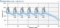
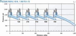
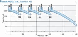
Figs. 1 and 2 compare pressure vs. distance for two designs for the 1,000-mile example pipeline.
Fig. 1 shows a low-pressure X-70 design with six compressor stations. Values on the graph indicate mileposts for the intermediate compressor stations.
Fig. 2 shows a higher pressure, smaller diameter X-120 design for the same gas throughput. The higher-pressure design requires only five stations.
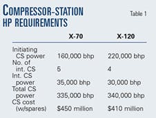
Table 1 compares calculated station horsepower requirements for both pipelines.
Total power requirements are nearly identical for the two cases, but the X-120 design has 9% lower cost because of economies of scale in the initiating station and elimination of fixed costs from reducing the number of intermediate stations. The difference in compression costs results in an added $40 million savings above those realized from reduced material and construction costs.
These additional savings equal 2% of total project cost for the example pipeline.
Integrated project
In addition to reducing pipeline costs, the high-pressure capability of X-120 pipe offers opportunities to consider alternative approaches to gas resource development and achieve savings on an integrated project basis.
A gas pipeline is one part of an overall project involving drilling, production, and transportation of gas to market. Typically, production from natural gas reservoirs includes varying amounts of NGL that must be removed from the produced gas to create a marketable sales gas. NGL are either reinjected or sold, depending on quantity and quality.
The processing and treating of natural gas and the handling of extracted NGL are integral to a gas resource development. In a conventional design, the gas-treating steps are performed in a field gas plant. The end products are "dry" sales-quality gas and stabilized NGL.
The gas is shipped via pipeline to market, an existing gas grid, or a storage facility. NGL not reinjected into the reservoir are sent to a fractionation plant for further processing into marketable products. Transportation of NGL is usually via a separate pipeline but can be by truck or rail.
Fig. 3 shows a conventional two-pipeline gas-field development.
[Editor's note: See accompanying field gas processing poster published with the Dec. 8, 2003, issue of Oil & Gas Journal.]
High-strength steel and the ability to design to much higher pressures allows consideration of alternative development options. The single line, high pressure dense-phase concept (Fig. 4) enables the gas and NGL to remain combined in a single-phase dense fluid, giving savings in both pipeline and facilities costs compared to a development using two single-phase pipelines.
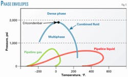
Dense-phase pipeline operations can be described by a set of conditions of pressure and temperature in which the transported fluid is in a single phase exhibiting characteristic properties between a vapor and a liquid. To explain dense-phase flow, Fig. 5 shows the phase envelopes for an example gas resource.
The field gas plant in the conventional concept separates reservoir fluid to create the pipeline gas (red) and pipeline liquid (green). Points outside a phase envelope are pressure-temperature combinations that indicate single-phase conditions, while points inside a phase envelope indicate multiphase conditions.
Pressures and temperatures associated with conventional pipeline operations (yellow area) are sufficiently high to maintain single-phase flow in the gas and liquid pipelines.
In the dense-phase concept, combined reservoir fluid (blue phase envelope) moves in a single pipeline. At conventional pipeline pressures, the combined fluid would be in multiphase flow, but if the minimum pipeline pressure is kept above the cricondenbar of the combined fluid, the fluid can move as a single "dense phase" (blue area).
An advantage of X-120 pipe is that designs at the high pressures required for dense-phase flow can be achieved with low pipe wall thickness at the pipe diameter required for full flow.
Using dense-phase flow results in several potential benefits in addition to pipeline cost reduction, including:
- Relocation of process facilities, such as NGL separation and stabilization, from remote field locations or offshore platforms, to locations more central to the market place.
- Combination of relocated facilities with existing infrastructure and facilities.
- Designing energy recovery into the process facilities to take advantage of the higher-pressure inlet stream.
Another application in which dense-phase flow may be beneficial is when pipeline temperature control is important.3 4 An example of savings from a dense-phase pipeline operation is discussed presently.
Examples
These three examples, based on actual case studies, demonstrate the potential economic incentives of an X-120 steel pipeline at higher pressure. The assumed price differential between X-120 and X-70 is $250/tonne.
Two measures evaluate high-strength-steel incentives:
1. A comparison of project capital cost, which is the nondiscounted sum of the capital expenditure (CAPEX) stream.
2. A comparison of present value life cycle cost, which is the present value (discounted at 10%) of the CAPEX stream plus 25 years of operating expenditures (OPEX) and fuel costs (with fuel valued at $1.00/ Mcf).
The difference between project capital cost (nondiscounted) and life-cycle cost (discounted) depends on the time duration and relative magnitude of the expenditures that make up life-cycle cost and on the discount rate used.
Onshore pipeline
For an onshore pipeline delivering 3 bcfd of gas from a remote field 2,000 miles from market, a conventional design might use X-70 line pipe at an operating pressure of 1,450 psi.
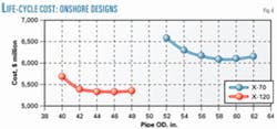
The solid curve in Fig. 6 shows life-cycle costs for six sizes of X-70 line pipe. The lowest life-cycle cost design would use 58-in. pipe and nine compressor stations. The capital cost is $6.77 billion, and the present value life-cycle cost is $6.04 billion.
The dashed curve in Fig. 6 shows life-cycle costs for five sizes of X-120 line pipe. The lowest cost X-120 pipeline design uses 46-in. pipe operating at 2,800 psi and seven compressor stations. The capital cost of this design is $6.01 billion; the present value life-cycle cost is $5.32 billion.
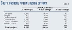
For this application, the use of high-strength steel results in a $760 million (11%) reduction in capital costs and a $720 million (12%) reduction in life-cycle costs. Table 2 provides a comparison of project cost and savings by category.
Offshore pipeline
The gas prospect is 800 miles offshore in 500 ft of water. A pipeline is to deliver 1.3 bcfd of gas to a shore location for sales into a local market. An island chain near the midpoint of the pipeline route enables the placement of an intermediate compressor station.
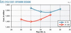
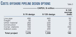
The solid curve in Fig. 7 shows life cycle costs for four sizes of X-70 line pipe. The lowest life-cycle cost design uses 36-in. X-70 line pipe and an operating pressure of 2,600 psi. Capital cost of this design is $1.47 billion; the present value life-cycle cost is $1.54 billion.
The dashed curve in Fig. 7 shows life-cycle costs for four sizes of X-120 line pipe. The alternative X-120 design uses 32-in. pipe operated at 3,300 psi. Capital cost of this design is $1.33 billion; present value life-cycle cost is $1.45 billion.
For this application, the use of high-strength steel produces a $140 million (10%) reduction in capital costs and a $90 million (6%) reduction in life-cycle costs. Table 3 provides a comparison of project cost and savings by category.
An important difference between the onshore and offshore examples is that there is limited opportunity to adjust compressor station locations in the offshore line. Offshore, the increased cost of the initiating compressor station for a higher pressure design can only be overcome by reduced material and construction costs. The same effect is seen in short onshore pipelines.
Integrated project
A gas prospect lies in a remote location, 650 miles from market. The terrain between the field and the market limits access to the field and makes construction difficult. At the design delivery rate of 1.7 bcfd, the reservoir gas contains about 60,000 b/d of NGL. The economics of the project will be enhanced if these liquids are sold.
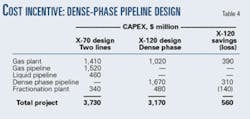
The conventional two-line concept (Fig. 3) would use a 36-in., X-70 gas line operating at 2,200 psi and a 16-in. liquid line operating at 3,000 psi. Capital cost of this two-line development is $3.73 billion; life-cycle cost is $4.25 billion.
The dense-phase concept (Fig. 4) would use 32-in., X-120 line pipe operating at 4,500 psi. The design pressure would maintain a minimum pipeline pressure of 2,700 psi keeping the fluid in a dense phase. Capital cost of this development is $3.17 billion; life-cycle cost is $3.68 billion.
Use of X-120 steel results in a $560 million (15%) reduction in project capital costs and a $570 million (13%) reduction in life-cycle costs.
Table 4, which compares project cost and savings by major components, makes two important points:
1. A dense-phase pipeline built with X-120 steel yields capital cost savings of $310 million over separate single-phase X-70 gas and liquid pipelines.
2. The ability to transport dense-phase fluids cost effectively using high-strength steel enables relocation of some process steps from the remote field location to a location close to infrastructure and the market. This relocation of process equipment provides an additional $250 million savings in project capital costs.
References
1. Fairchild, D.P., Macia, M.L., Papka, S.D., Petersen, C.W., Stevens, J.H., Barbas, S.T., Bangaru, N.V., Koo, J.Y., and Luton M.J., "High Strength Steels – Beyond X-80," International Pipe Dreamer's Conference, Nov. 7-8, 2002, Yokohama.
2. Engineering Data Book: FPS Version; Tulsa: Gas Processors Suppliers Association, 1998.
3. King, G., Kedge, K., Zhou, X., and Matuszkiewicz, A., "Superhigh Pressure Dense Phase Arctic Pipelines Increase Reliability and Reduce Costs," 2002 International Pipeline Conference & Exposition, Sept. 29-Oct. 3, 2002, Calgary.
4. Penick, D.P., and Thrasher, W.B., "Background and Advantages of Operating Gas Pipelines at High Pressure," London: Institute of Petroleum, 1981.
The authors
Kevin T. Corbett currently works with the technology applications division of ExxonMobil Upstream Research Co., Houston. He joined the company in 1980 and has held research positions in directional drilling, artificial lift, and pipelines. He provided planning support for the Chad pipeline project for Exxon Co. International 1991-94. He was employed by Rockwell International 1974-80. Corbett holds a BS in electrical engineering from the University of Notre Dame, South Bend, Ind., and an MSc (1974) in ocean engineering from the University of Rhode Island.
Ron R. Bowen currently serves as senior research manager with ExxonMobil Upstream Research Co., having joined Exxon Co. USA in 1976. He has worked in gas treating, processing, and transportation. Bowen holds a BS (1976) in mechanical engineering from the University of Texas and served 7 years in the US Navy nuclear submarine service.
Cliff W. Petersen has, since 1995, coordinated the high-strength steel development project for ExxonMobil, which he joined in 1976. He has also supervised sections within the company pertaining to new drilling systems, drilling engineering, and materials. He worked 1974-76 for Westinghouse at the Bettis Atomic Power Lab performing research in support of the US Navy's nuclear program. Petersen holds a BS in mechanical engineering from Marquette University and MS and PhD degrees in ocean engineering from the University of Rhode Island, specializing in materials and metallurgy.
