Hubs, new technologies provide access to more deepwater reserves
Hub installations along with advancements in well completions, pipelines, flowlines, and producing facilities are helping economically to develop smaller deepwater accumulations, especially in the Gulf of Mexico.
Most deepwater areas in the world still rely on subsea developments tied-back to floating production, storage, and offloading vessels. But in the Gulf of Mexico, the pipeline infrastructure continues to reach out into deeper water, allowing producers to obtain acceptable infrastructure costs and processing terms for smaller discoveries.
Deepwater, depth greater than 400 m (1,312 ft), remains a relatively new frontier for the industry, but it is maturing quickly since the initial start of exploitation in the 1980s. One estimate is that the potential recoverable reserves in this frontier, worldwide, are about 150 billion bbl of which about 50-60 billion have been discovered and 3-4 billion bbl have been recovered to date.1
The industry, according to one estimate, has discovered about 11 billion bbl of oil in the deepwater Gulf of Mexico.2
The US Department of Energy (DOE) estimates potential remaining recovery for the gulf may be 28 billion barrels and that by 2005 as much as 67% of daily oil production and 26% of daily gas production in the gulf will come from deepwater fields. The US outer continental shelf (OCS) beyond a 400-m water depth contains 21.5 million acres, which is greater than the 18.6 million acres in water depths less than 400 m.
The Gulf of Mexico, West Africa, and Brazil remain the most active areas, although other deepwater basins have discoveries and producing fields. But in all areas, estimates indicate that operators will order a large number of subsea trees in the near future (Table 1).
In the gulf, there are about 49 fields with subsea-completed wells, of which 25 are tied-back to OCS hub platforms.3
Producing deepwater has changed over time as developments have moved into ever increasing depths, such as the ultradeepwater with depths greater than 900 m (2,953 ft).
Changing production schemes
One can see the changes in deepwater operations that have taken place by examining the history of some early deepwater installations in the Gulf of Mexico. For instance, the Bullwinkle platform has changed in several respects since production started through it in 1989.
This Shell Exploration & Production Co. (Sepco) platform remains the tallest pile-supported, fixed steel platform in the gulf. It sits in 1,353 ft of water in Green Canyon Block 65. Total height of the structure is 1,736 ft, from the sea bottom to the top of the flare boom.
Shell initially estimated that the ultimate recovery from the $500 million project would be 115 million bbl of oil and 195 bcf of gas. This is a relatively small accumulation compared to current expectations in the deepwater, especially in the ultradeepwater that includes the 1 billion boe recoverable reserves in the BP PLC-operated Thunder Horse development in Mississippi Canyon Block 822 and the large discoveries and producing fields off West Africa and Brazil.
Fig. 1 compares Bullwinkle's size to other deepwater discoveries in the gulf.
The Bullwinkle platform has 60 well slots but Shell only drilled 25 wells on about 80-acre well spacing from the platform with an initial processing capacity of 59,000 bo/d and 100 MMcfd. It lists that the highest single-well production rate was 8,425 bo/d on Aug. 11, 1994.
If developed today, the field conceivably could be developed with three to five subsea wells, on 600-1,000-acre spacing, tied back to shelf facilities because such technological advances as running 4 in. and 7-in. tubing strings, shooting larger perforations, long openhole gravel packs over multiple reservoirs, frac packs, and smart wells have greatly increased the productive capacity of deepwater wells that may produce at peak rates of 15,000-40,000 bo/d and be expected to recover 15-40 million bbl/well.3
Shell says oil and gas production from Bullwinkle peaked at 56,600 bo/d and 100 MMcfd in November 1993, and as production declined it converted Bullwinkle into a hub for multiple subsea development.
In January 1996, the platform started handling oil and gas from Shell's deepwater Rocky subsea completion in Green Canyon Block 110, about 4 miles away in 1,785 ft of water.
In 1996, Shell increased the platform's processing capacity to 200,000 bo/d and 306 MMcfd at a cost of about $95 million to accommodate production of 14,000 bo/d and 22 MMcfd from Bullwinkle, 3,800 bo/d and 5.5 MMcfd from Rocky, and 80,000 bo/d and 142 MMcfd from BP-operated Troika subsea production in Green Canyon Block 200, about 15 miles from Bullwinkle. Production from Troika started on Nov. 10, 1997.
Shell added production from its operated Angus subsea development 12 miles away on Green Canyon Block Block 113, in September 1999. Two more subsea fields followed this: Shell-operated Manatee and BP-operated Aspen in 2002.
It says that the facility expansion added about 4,000 tons of equipment and piping, covering more than 30,000 sq ft. New equipment included production separators, inlet heaters, gas compressors, launcher receivers, control building, additional separators, hydraulic power units for subsea wells, bulk-oil treater, flash-gas compression, electrical generation equipment, a 20-ton crane, chemical storage, and pumps for hydrate prevention, corrosion inhibition and paraffin dispersion, and additional pipeline pumps.
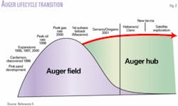
In a similar fashion, Shell modified the Auger tension-leg (TLP) platform to become a hub for several subsea fields as the production from its original wells declined (Fig. 2).5 To utilize the platform fully, Shell has formed a production handling agreement (PHA) business development group that has negotiated with midstream pipeline companies to bring in outside production for processing on the Auger platform.6
In its newer production facilities, such as the Brutus TLP (OGJ, Sept. 10, 2001, p. 66), Shell already designed provisions for the facility to handle outside production from the start. Also such facilities as the Na Kika semisubmersible production unit are designed for multifield development from the start of production (OGJ, Sept. 15, 2003, p. 73.).
Third-party hubs
GulfTerra Energy Partners LP, formerly El Paso Energy Partners LP, aims to develop processing hubs in the Gulf of Mexico that can be particularly attractive to independents that prefer to invest their capital in drilling wells instead of building their own processing facility, according to Bart Heijermans, vice-president offshore for GulfTerra Energy Partners LP.
GulfTerra already owns several platforms along the edge of the OCS that process deepwater production and also serve as junctions for its extensive pipeline network in the gulf.
It recently installed its 100%-owned Falcon Nest platform, in 390 ft of water on Mustang Island Block 103 with a 400-MMcfd processing capability, to handle gas produced from Pioneer Natural Resources Co.'s Falcon field in 3,400 ft of water on East Breaks Blocks 579 and 623 (OGJ Online, Dec. 17, 2002) and other future developments. Reserves in Falcon are estimated at 175-240 bcf.
Heijermans said by entering into the processing agreement the producers de-levered their balance sheet, lowered their finding and development costs, and freed up capital for drilling additional prospects.
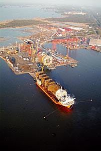
The hull of the Marco Polo TLP was brought to a construction yard in Ingleside, Tex., after being built in South Korea. (Fig. 4). Photo courtesy of GulfTerra Energy Partners LP.
Its latest venture is the Marco Polo TLP, owned by Deepwater Gateway LLC, a joint venture owned by GulfTerra and Cal Dive International Inc. The TLP, in 4,300 ft of water, will process gas from Anadarko Petroleum Corp.'s Marco Polo field in Green Canyon Block 608.
Heijermans explains that in this case Deepwater Gateway will bear the $210 million capital cost of the platform, including the six production risers, while Anadarko will spend its capital on drilling wells in the Marco Polo area.
Deepwater Gateway oversized the Marco Polo processing capacity to 100,000 bo/d and 300 MMcfd instead of the 50,000 bo/d and 150 MMcfd required by Anadarko. Heijermans said that to build the first 50% of the processing capacity represents about 80% of the capital cost, while the additional 50% represents only 20% of the capital cost.
Anadarko will pay Deepwater Gateway a fixed fee and a processing fee. It will also operate the facility with its own crew.
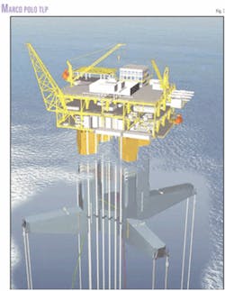
The Marco Polo TLP (Fig. 3) is a MODEC International LLC Moses design. Fig. 4 shows the hull of the platform as it is being transported to the Kiewit Offshore Services yard, Ingleside, Tex.
Production from the field will be from six predrilled wells with dry trees and dual casing production risers. The TLP accommodates 12 future flowline risers and has 6 preinstalled I-tubes for umbilicals.
The 18 and 20-in. gas and 14-in. oil export pipelines connect to 18-in. and 123/4-in. steel catenary risers.
The platform is anchored to the seafloor with eight 28-in. diameter tendons with a 1.2-in. WT that are connected to 390 ft by 76-in. diameter piles with a 2-in. WT.
The 5,750-ton hull has dimensions of 344-ft in width and 196 ft in height from the bottom of the base to the top of the column. The three level topsides has a 6,300-ton lift weight and a 7,250-ton operating weight.
Deepwater Gateway expects to install the TLP on site during November.
New designs
The design of floating structures for supporting deepwater processing facilities has changed over the years. One new design is the cell spar (Fig. 5) that Kerr-McGee Corp. expects to install in the Red Hawk field in second quarter 2004.
Kerr-McGee introduced the first two versions of the spar: the classic spar in 1996 on the Neptune field (OGJ, Nov. 24, 1997, p. 72) in 1,930 ft on Viosca Knoll Block 856 and the truss spar last year in Nansen field in 3,700-ft of water on East Breaks Blocks 601, 602, and 646.
Kerr-McGee explains that an open-truss structure compared to the classical spar reduces hull weight, lowers fabricating costs, reduces loop current loads on the hull, dampens heave response, enhances the spar's stability, allows adjustment of the heave period, and provides a shallower draft.
The company estimates that the use of this design enabled it to begin production less than 2 years after sanctioning development.
The spar also provides excess processing capacity for handling production from satellite subsea completed fields.
In 2002, Kerr-McGee installed a similar truss spar in nearby Boomavang field and in October 2003, a truss spar in the Gunnison field. It expects production from Gunnison to start in early 2004.
The Boomavang field covers East Breaks Blocks 642, 643, and 688, and the Gunnison is on Garden Banks Block 688 in 3,150 ft of water.
The accompanying box describes the installation procedure for the Gunnison spar.
The Red Hawk cell spar will develop a gas field in 5,300 ft of water on Garden Banks Block 877 with 250 bcf of estimated recoverably reserves.
Kerr-McGee operates Red Hawk, with a 50% interest, and its partner, Devon Energy Corp. holds the remaining 50%.
null
Gulf Marine Fabricators' yard in Ingleside, Tex., is constructing the hull of the cell spar, thus eliminating the long ocean voyage required in transporting spar hulls from Finland to the Gulf of Mexico (Fig. 6).
The Red Hawk spar hull is made up of seven hollow tubes or cells, each with a 20-ft diameter.
Six tubes wrap around a central tube with structural steel connecting all of them together.
To add stability, the design includes four 280-ft long tubes and three 560-ft long tubes.
For mooring the cell spar will have six mooring lines consisting of 1,260 ft of steel chain and 7,100 ft of 8.5-in. polyester rope, weighing 5.2 lb/ft. Kerr-McGee says that the polyester rope increases the strength-to-weight ratio and enhances the performance characteristics of the mooring system.
The cell spar will have a 120 MMscfd initial and a 300-MMscfd future processing capacity.
References
1. Jacobsen, D., panel session remarks, SPE Gulf Coast Section deepwater conference, Houston, Apr. 16, 2003.
2. Siegele, P., "Industry Perspective," MMS Workshop on Deepwater Environmental Studies Strategy: A Five-Year Follow-Up and Planning for the Future; New Orleans, May 29-31, 2002.
3. Heijermans, B., et al., "The Commercial Development of Hub Platforms and the Value to E&P Producers," Offshore Technology Conference, Houston, May 5-8, 2003.
4. Sieler, J., "Deepwater Reservoir and Well Performance Where Have We come Since Bullwinkle," SPE Gulf Coast Section meeting, Houston, June 10, 2003.
5. Williamson, K., "Multiphase Metering of Subsea Flowlines - The Auger Experience," Texas A&M Mulitphase Measurement Roundtable," Houston, May 6, 2003.
6. Brock, V.A., "Auger-An Asset in Transition," Offshore Technology Conference, Houston, May 5-8, 2003.
Gunnison spar installation
null
The following steps outline the installation procedure for the Gunnison spar.
1. Piling installation Apr. 1-18, 2003, with the Cal Dive dive support and multi-service vessel (DSV/MSV) Q4000 and dynamically positioned and remotely operated vehicle service vessel (DP/RSV) Merlin. Drive nine piles with subsea hammer, in three clusters of three piles. Each pile is 220 ft long and weighs 135 tons.
2. Hull transportation May 25 to June 19, 2003, by Dockwise Shipping BV heavy-lift vessel (HLV) Mighty Servant 1. Load spar hull from quay to HLV and begin trip on May 25 from Pori, Finland, with arrival at the Gulf Marine Fabricators yard in Corpus Christi, Tex., on June 18. Complete export pipeline installation.
3. Moorings installation with Heerema DP derrick crane vessel (DCV) Balder. Connect mooring wire to pile chain segments on seafloor. Lay out chain-wire-chain on seafloor.
4. In October 2003, spar tow, upend, moor, ballast with Heerema DP DCV Balder. Tow spar to site. Pull four 36-in. and four 6-in. ripouts to upend spar. Install one mooring per cluster of three. Repeat until all nine are connected. Pump 213 tons of hematite fixed ballast into keel tank. Pretension mooring system. Pick up and hang steel catenary risers
5. Install lower stems, topsides, living quarters, air cans, and upper stems with Heerema: DCV Hermod. Tow out topsides, stems, and cans on barges. Pre-install seven 326.5-ft lower stems. Lift and install 5,543-ton topsides, followed by 533-ton living quarters. Install and connect 187.5-ft air cans and 97-ft upper stems.
6. Obtain temporary Certificate of Inspection. Set up gangway between Q4000 and the spar. Offload temporary quarters. Complete tasks required by American Shipping Bureau (ABS) and US Coast Guard. Move onto Gunnison spar and demobilize Q4000.
7. Subsea equipment installation with Cal Dive DP DSV Northern Canyon and DP DSV Intrepid. Install flexible and steel flowlines, umbilicals, and risers. Install jumpers and flying leads between trees and pipeline-end terminations. Hydro test, dewater, and prepare for production.
8. Complete all remaining tasks to clear ABS and US Coast Guard requirements to obtain permanent Certificate of Inspection.
9. Rig-up support remotely operated vessel on spar. Rig-up Nabors 1,500-hp MODS 150 workover rig.
10. Complete spar wells with workover rig. Run risers and complete seven wells with first production in early 2004.


