Positional inaccuracies lead to poor drilling decisions
WELLBORE POSITIONING—2
Rotary drilling with positive-displacement motors can introduce positional inaccuracies that remain undetected with stationary surveys and lead to potentially mistaken drilling decisions.
Part 1 of this series, (OGJ, Oct. 27, 2003, p. 51) revealed where positional inaccuracies occur in horizontal wells and how frequently they happen when drilling with a conventional steerable, positive-displacement motor system.
This article further illustrates positional issues using PDMs and then discusses rotary steerable systems and the impact of lithology on accurate well placement.
The final installment in an upcoming issue will offer recommendations and techniques for minimizing the problem of positional inaccuracies.
Tangent sections
A tangent section is the angle hold section in a standard slant or "S" trajectory, or the lateral section of a horizontal well. It is generally expected that when rotary drilling with a conventional steerable PDM assembly, the borehole angle and direction will be maintained. However, it is sometimes necessary to use active directional drilling; that is, perform slide sections when the objective is to hold angle in a tangent section.
The build or drop and turn tendency of a bottomhole assembly (BHA) can change with differing formations and operational parameters such as flow rate, weight-on-bit, and rpm.
To counter undesired rotary drilling tendencies, a directional driller can add short slide sections to the drilling sequence.
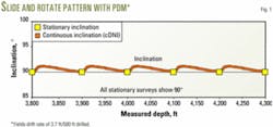
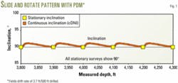
Fig. 1 shows a model of what stationary and continuous survey data can look like when rotary drilling a lateral section with a BHA that drops at 1º/100 ft.
To maintain the wellbore at 90º, the driller has added a slide section of 14 ft, building at 6º/100 ft, to neutralize a rotary section of 86 ft dropping at 1º/100 ft in a 100-ft drilling section.
Here the slide is placed immediately after the stationary survey depth. All stationary surveys read 90º when this pattern is repeated, and it would be assumed that the wellbore is perfectly flat.
The continuous surveys show the actual inclination for this pattern and have values greater than 90º, except at the stationary survey points.
The wellbore TVD position calculated from the continuous surveys will drift shallow as compared to the position calculated from the stationary surveys. In this case the drift rate is 3.7 ft/500 ft drilled.
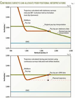
The Fig. 2 models demonstrate how this drift can impact decisions in drilling a horizontal well.
Fig. 2a shows the well trajectory interpretation that likely would result using stationary surveys to guide the planned placement of a 1,500-ft lateral section below the top of a relatively horizontal pay zone and above the oil water contact (OWC).
The stationary surveys show that the wellbore has been held at 90º with no change in TVD, yet the wellbore exits top of pay after drilling only 810 ft. The logical conclusion would be that the formation dips downward. Drilling would be stopped, and recoverable reserves estimates would be lowered since the full, 1,500-ft lateral drainage field was not achieved.
Fig. 2b shows the interpretation with the same drilling scenario using continuous surveying in a post-mortem analysis. It indicates that the well path had drifted upward and that the original structural interpretation was correct.
By monitoring well position in real-time with the continuous (cDNI) measurements, one can avoid negative scenarios like these in the future.
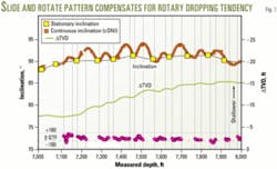
Fig. 3 shows an actual case of using slide sections to compensate for a rotary dropping tendency during planned hold sections.
Relatively long slides maintain approximately 90º to offset a relatively strong dropping tendency while rotating the BHA.
This well was eventually sidetracked when the top of pay was encountered earlier than expected.
Rotary steerable systems
Rotary steerable (RS) systems have eliminated the need for large curve rate changes between slide and rotary drilling sections, which are required with steerable motors.
RS systems produce curve rates by selecting a tool face angle and percentage of side force in the direction of the tool face angle.
To increase angle and turn slightly to the right, a tool face of 20º could be used with 35% of total force available.
The power setting would be changed to 100% in order to steer more aggressively. A neutral setting of 0% and the tool face angle would be irrelevant.
One would expect the BHA to maintain a relatively constant hole angle and direction.
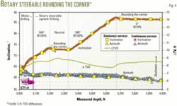
Directional drilling with an RS system can produce long, consistent curve rates that are smooth and predictable. These systems also allow greater overall penetration rates for a well; however, a TVD difference can develop when settings change between survey points, as in Fig. 4.
That figure shows an example from a North Sea well during its final build to horizontal. A bit run with a steerable motor finished at about 3,100 ft and was followed by an RS run.
Four different tool settings were subsequently applied over the 3,100-4,000 ft interval. The continuous inclination measurements demonstrate the consistency in build angle for each set.
Stationary surveys were taken after drilling each pipe stand. In two cases the steering settings were changed between stationary survey points resulting in an apparent "rounding the corner" effect between the continuous and stationary inclinations.
Such corners can cause up to a 2-ft TVD difference-occurrence and in this case accumulated to about a 3-ft TVD difference.
Effects of lithology
Lithology changes such as tight streaks, changes in rock strength, and changing bed dip angle can alter directional tendencies.
When these are encountered between survey stations, a rounding the corner effect, similar to what happens with RS systems, can result in TVD positional differences.
Typically isolated incidents, these events are difficult to detect with long survey intervals.
Tight streaks can result in a large dogleg over a short interval and cause drilling and completion problems in addition to TVD differences.
By monitoring the cDNI data in real-time, these events can be identified and remedial action taken to minimize their effects.
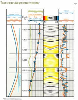
Fig. 5 shows the reaction of an RS drilling assembly with a high-density tight streak in a horizontal wellbore. The trajectory decreases to 82º from 95º inclination while drilling a sinusoidal horizontal well profile.
The bit hits the bottom of a hard streak at 5,750 ft and bounces down, as shown by the continuous inclination. Bottomhole assembly (BHA) stiffness causes the inclination to recover and the bit hits the hard streak a second time before the general downward tendency in inclination continues.
The stationary surveys do not register this event. In this case, the TVD positional differences cancel out. The dip interpretation, using an image log and stationary surveys, would indicate folded beds and dip changes. Interpretations of continuous surveys, on the other hand, would indicate that the bed dip is constant and the wellbore is kinked.
