Staged modifications improve BTX extractive distillation unit capacity
A well-planned and executed test run of existing equipment followed by a distillation fundamentals review can yield cost-effective production increases.
On an existing extractive distillation benzene-toluene-xylene (BTX) column, the aromatic production capacity increased more than 18% while aromatics recovery improved.
Improved distributor design allows increases in the efficiency and capacity of structured packing. Enhanced mixing of vapor and liquid phases results in improved mass transfer.
An Asian petrochemical producer commissioned a new grassroots BTX extractive distillation unit in February 2000.
The operator performed a test run in July 2000, at which time the plant's design criteria were marginally accomplished. Modifications, made in two steps to improve unit performance, allowed the plant to meet all design criteria.
Field inspection and revamp engineering identified the required modifications. Attention to detail is required to meet capital goals fully.
Background
The grassroots extractive distillation unit, commissioned in January 2000, consists of a reactor pretreatment section, an extractive distillation (ED) column, a stripper column, and a benzene-toluene distillation column.
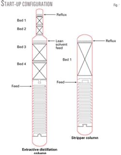
The ED column had four structured packed sections in the rectifying section and trays in the stripping section.
The stripper column had one structured packing bed with one active tray in the rectifying section and trays in the stripping section.
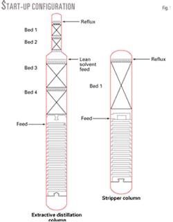
Fig. 1 shows the ED and stripper columns.
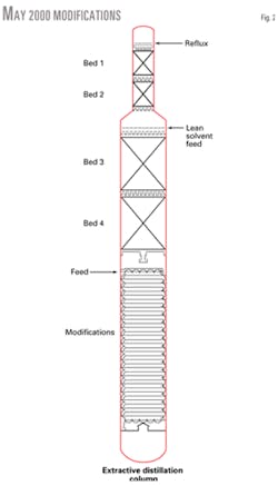
After initial commissioning, the unit failed to meet design rates and recoveries. We identified problems, reviewed operations, and decided that using new Z-Bar type trays, with small slotted valves to replace the lower trays of the ED tower would enable the unit to meet design conditions.
Z-Bar trays have additional area in the downcomer to allow more liquid traffic. Small slotted valves, which are smaller than standard valves, have higher overall efficiency.
The operator shut down the unit in May 2000 for tray replacement. Fig. 2 shows the changes that were implemented.
May 2000 inspection
A team of maintenance and engineering personnel inspected the ED column and stripper column in May 2000. They found that the columns were clean and well constructed. The design was similar to those that had been successful in similar processes in the past. It is acceptable to use past designs if they conform to engineering fundamentals.
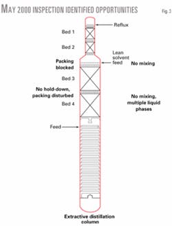
The inspection identified opportunities for improvements beyond the tray replacement scheduled for the turnaround.1 Five of the ED column opportunities were important enough to plan for future work (Fig. 3).
The first opportunity was at the top of Bed 3 in the ED column. This was the lean-solvent feed point. The liquid distributor had 4 by 8-in. plates on top of the packing supporting the distributor, which blocked 8% of the column cross-sectional area. This created two limits—reduced capacity due to blocked cross-sectional area and channeling around the large support plates.
Blocking the cross-sectional area increases liquid and vapor velocities in the open areas. Higher velocities load the column, which causes flooding at lower rates vs. unblocked operations.
Channeling reduces packing efficiency. This occurs when the vapor and liquid travel in separate paths and fail to mix. As liquid travels down the packing bed, less and less mixing occurs, which reduces heat and mass transfer.
Liquid coalesces into large flow streams that bypass rising vapor. Blocked areas create dry spots in the packing and channels vapor and liquid. This limits high-efficiency application performance.
The second opportunity was in the Bed 3 distributor. The distributor had two feeds: from the second bed of packing, which was mostly hydrocarbon, and from the lean-solvent feed point.
The distributor was essentially two parallel distributors; i.e., feed to the third bed was not premixed. This meant that hydrocarbon from Bed 2 and lean solvent did not come into contact until several feet down the bed of packing.
The third opportunity was at the bottom of Bed 3, which did not have a liquid collector. Liquid could freely rain down on the next distributor tray, which created a potential for packing inefficiency.
A liquid collector-distributor has two functions. The first function is to collect, mix, and reroute liquid to the next bed.
Failure to remix the liquid perpetuates packing inefficiencies between beds. Small distribution inequalities in a packed bed can create composition gradients across a tower.
Composition gradients also result from liquid distribution reaching a natural distribution quality in deep packed beds. Remixing at a collector prevents composition pinches created in one bed from reducing the effectiveness of other packed beds.
The second function of a liquid collector is to distribute vapor evenly across the upper bed section. In some towers that lack a collector, vapor may channel, which can lead to lower packing efficiency and tower capacity.
Vapor distribution is most important when operating with:
- Insufficient height for vapor mixing between the beds.
- High-pressure applications with high gas densities.
- A small gas-to-liquid density ratio.
The fourth opportunity was in Bed 4. The distributor was a chimney tray. At that point in the tower there were two liquid phases—hydrocarbon and solvent. A standard chimney does not work well for two liquid phases with different densities.
The fifth and last opportunity was that Bed 4 did not have a hold-down grid on top of the packing. Hold-down grids maintain packing levelness during mild column upsets. The packing appeared to be disturbed under the chimney tray.
We recommended rectifying each problem. Time constraints, however, restricted work to the originally scheduled replacement of 37 trays in the stripper column. After tray replacement, the unit was recommissioned.
Turnaround time management
During a turnaround, decisions are normally made quickly in light of lost production, with the consideration that the shortest and most reasonable outage will result in improved tower performance.
It is difficult to extend an outage when a unit is shut down and no saleable products are being produced. The unit manager must balance the cost of additional lost production vs. the potential gain of improved tower performance. It is often difficult to quantify the potential gain of improved tower performance.
It is important for a decision maker to consider potential scenarios before a turnaround begins. Some of the scenarios that may cause additional time in the outage include:
- Damaged trays.
- Upset packing.
- Damaged feed and reflux nozzles.
- Improper installation.
- A design that deviates from basic principles.
Managers are group leaders that assemble teams of people for the best overall result.2 Before the problems occur, managers must built relationships with competent specialists so they can accurately and quickly quantify the potential gain of improved performance. Decisions with reliable guidance improve plant profits.
Tower troubleshooting
Problem-solving efforts should continue after a plant restarts. Troubleshooting and revamp engineering should constitute a continuous activity.
Troubleshooting often refers to smaller-scale activities
The first step in resolving any distillation problem is to understand the column's operating and technical fundamentals.5 Knowledge of how a column functions, hydraulic constraints, thermodynamic and equilibrium limits, and heat and material balances are required.6
This knowledge must be accumulated before formulating any resolution to a problem.
Four common types of distillation equipment problems include inappropriate design, improper installation, ineffective operation, and equipment damage.
Before a process is shut down for repairs the operator must find inappropriate designs and eliminate inappropriate operations.
One should always do simple checks first:
- Ensure that level gauges are accurate. Have operations move levels and view changes in the field.
- Calculate column pressure drop and then measure pressure drop. Review survey pressure readings compared to operation's readings.
- Survey column temperature profile. Compare the review survey temperature readings to operation's readings.
These simple steps can identify many problems.
Only after the performing of the low-technology hydraulic and operating evaluations should efficiency calculations begin. Simulators are a terrific tool in capable hands, but they are rarely the place to start.
Sometimes the feed composition changes and the tower can no longer meet desired specifications due to thermodynamic or equilibrium constraints. Parameters required to perform a tower simulation are:
- Accurate tower feed, overhead, and bottoms laboratory analysis.
- An accurate tower mass balance, within 2%.
- Heating and cooling medium temperatures.
Only when the tower simulation confirms that the limits are not beyond thermodynamic or equilibrium constraints should the operator consider advanced methods such as gamma scans.
For certain applications, this type of troubleshooting method can determine internal damage, vapor-liquid maldistribution, and packed and trayed tower fouling.
Because of economic constraints, scanning should be used only after the simple checks and the limits are confirmed. Scanning can sometimes confirm problems that the other checks identified.
May 2000–January 2001
During May-July 2000, the unit was optimized further, with several other nondistillation unit issues being resolved.
The operator performed a test run July 13-16, 2000. The unit demonstrated design rates but did not meet benzene recoveries.
Table 1 shows the results of the test run.
From July until December, the unit operated and the owner conducted more optimization efforts.
In November 2000, a high-load test determined the existing limits of each section in the plant.
A properly planned and executed high-load test can provide valuable information for unit revamps and troubleshooting.
A high-load test provides insight into the unit's current problems and underutilized equipment.
The operator increased the feed in steps during a 2-day period, Nov. 10-11, to test each section. The feed rate was slowly raised to 123% for a hydraulic system check.
The plant's limiting section was the stripper column, which had solvent carryover starting at 111% of base capacity.
During a January 2001 turnaround, the operator upgraded the BTX unit. Optimization work and a revamp analysis, including simulations, rated the ED and stripper column. Existing packing in the ED and stripper column was rated at 140% of design. New trays in the bottom of the ED column were rated at 125% of design.
The unit limits were the distributors and stripper trays. An additional problem was solvent carryover in the stripper column.
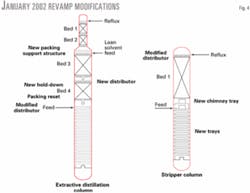
Fig. 4 shows the changes to the ED column and stripper column.
Stripper modifications
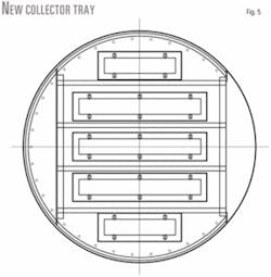
To reduce solvent carryover, the active tray below the packed bed was converted to a chimney tray.
A small amount of fractionation capacity was lost, but during the high-load test the aromatics in the lean solvent remained low.
A chimney tray design seems straightforward; however, several factors must be considered during its design. The designer must review and optimize the chimney tray's pressure drop for vapor distribution effectiveness. The designer must review vapor distribution and redesign the chimney hats if distribution is inadequate.
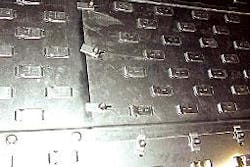
Figs. 5 and 6 show the new collector tray.
Remaining stripper column trays were upgraded to Z-Bar style trays with small valves to match the ED column trays.
Fig. 7 shows the Z-Bar tray deck. They were rated to 140% of design. One negative of increasing tower tray rates is the adverse affect on column downturn.
With an increased design rating, the new effective column minimum operating rate also increased.
ED column changes
We found several opportunities to improve operations in the ED column in May 2000; we addressed each opportunity during the January 2001 turnaround.
The liquid distributor support above Bed 3 was redesigned to reduce the area blocked by the support structure. This reduced the blocked area of the packing to less than 1%, which increased unit capacity significantly.
The feed distributor was reconfigured to allow hydrocarbon and lean solvent to premix when leaving the distributor.
Each distributor box had dual compartments that released the different phases to mix together above the packing.
This enhanced the solvent's ability to be more selective to aromatics. At that point there are three phases in the packing: vapor that should be mostly nonaromatics, hydrocarbon liquid that should be a mixture of aromatics and nonaromatics, and solvent.
Improved mixing of the phases leads to increased mass transfer.
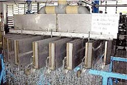
Fig. 8 shows the new distributor being tested.
The distributor for Bed 4 did not have liquid remixing and was not designed specifically for two liquid phases. Liquid was allowed to rain down freely onto next packed bed.
The operator removed the packing from Bed 3 and installed a liquid collector.
The well-mixed liquid was collected and routed to the Bed 4 liquid distributor, and the vapor was evenly distributed to the packing above the collector.
The Bed 4 distributor was a chimney tray. At that point there are two liquid phases: hydrocarbon and solvent. A standard chimney tray is an ineffective distributor for two liquid phases with different densities.
The plant owner replaced the distributor with a design that would evenly distribute the two liquid phases. Each overflow weir had two exit points, one for each density.
Bed 4 did not have a hold-down grid, which helps keep packing in place. We found that the existing packing had been upset. Packing was removed, reinstalled, and a hold-down grid was installed.
Additional work during the January 2001 turnaround was performed on the ED column feed distributor. The feed distributor was modified during the May 2000 outage.
We were concerned that the hydrocarbon feed had the potential to exist in two phases, vapor and liquid. The original design was a T-shaped inlet feed nozzle with outlet holes only in the bottom of the T.
null
In January 2001, the design was modified to include a vapor slot in the top of the T. In May 2001, a shroud was added to the distributor.
The operator commissioned the unit in February 2001 and performed a high-load test in May 2001. The unit has not yet reached its limit due to feedstock constraints.
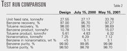
Table 2 shows a comparison of the July 2000 and May 2001 test runs.
null
Lessons learned
In each revamp there are lessons to be learned and noted.
Unfortunately, there are times when one learns the lesson only after the unit starts up. Here are some learned in this revamp:
- Review each design to ensure that it conforms to distillation fundamentals. Even if a design has been successful in the past, a review of each new application must be completed. Some small deviation could restrict the column from obtaining design goals.
- Operating companies should note that most distillation applications can be improved. For many existing columns, a test run followed by a review of distillation equipment can lead to improved rates and recoveries. New designs can improve the efficiency of existing columns.
- For engineering and construction companies, improved column efficiencies could translate into smaller equipment with lower construction costs, leading to advantages in the bidding wars for given projects.
- Building relationships with competent professionals in distillation, rotating equipment, furnaces, and other areas before a unit outage can yield timely guidance.
References
1. Hug, A., and Chua, M., "Optimizing Maintenance Operations in Refining," presented to the IBC Asia Pacific Conference, Chemical, Petrochemical and Power Sectors, Nov. 1-2, 2000, Singapore.
2. Gray, J., Kolmetz, K., Tong, S.N., and Mun, T.C., "Ethylene Plant Operation Management Concepts," presented to Titan Petrochemicals Sdn. Bhd., Apr. 7, 2001.
3. France, J.J., "Troubleshooting Distillation Columns," presented to the AIChE Spring National Meeting, Mar. 28-Apr. 1, 1993, Houston.
4. Kolmetz, K., Tong, S.N., and Mun, T.C., "Ethylene Plant Revamp," presented to the 5th Annual Asean Regional Olefins Conference, Oct. 31-Nov. 3, 2000, Johor Bahru, Malaysia.
5. Kolmetz, K., and Zygula, T.M., "Resolving Process Distillation Equipment Problems," presented to the 5th Annual Asean Regional Olefins Conference, Oct. 31-Nov. 3, 2000, Johor Bahru, Malaysia.
6. Gray, J., Kolmetz, K., Tong, S.N., and Mun, T. C., "Practical Distillation Fundamentals," presented to Titan Petrochemicals Sdn. Bhd., July 18, 2001.
The authors
Karl Kolmetz ([email protected]) is an assistant manager of process technology for Sulzer Chemtech Pte. Ltd. Singapore. His responsibilities include technical support for process equipment design and installation for the Asian Region. He previously worked for the Westlake-Titan Group, Raytheon Badger Construction Co., and Charter-Phibro Refining Inc., Houston. Kolmetz has a BS in chemical engineering from the University of Houston.
Mel Chua is the general manager of operations for Sulzer Chemtech Pte. Ltd. Singapore. His responsibilities include production, engineering, information technology, and turnaround services for the Asia-Pacific region. He has XX years' experience with Sulzer Chemtech in various positions. Chua holds a BS in mechanical engineering from the National University of Singapore.
Raghu Desai is a sales manager, Shell Technology for Sulzer Chemtech Pte. Ltd., Singapore. His responsibilities include technical support, marketing, and sales of Shell high-capacity trays and Sulzer mass transfer components in Asia-Pacific region. Previously he worked as a research assistant at the University of New South Wales, Sydney, Australia. Desai holds an MS in project engineering from the Birla Institute of Technology and Science, India, and BS in chemical engineering from Karnatak University, Dharwar, India.
Jeff Gray is a senior commissioning manager for KLM Technology Group, Melbourne. His responsibilities include plant commissioning, equipment performance checks and test runs, process design, project coordination, and operations and technical training. He previously worked for the Westlake-Titan Group, Exxon Corp., and Dow Chemical Co. Gray holds a BS in chemical engineering from the University of Melbourne.
