Coke trap reduces FCC slurry exchanger fouling for Texas refiner
Marathon Ashland Petroleum LLC's Texas City, Tex., refinery reduced fouling and cleaning frequency in its lead slurry pumparound heat exchanger by installing a coke trap.
The slurry exchangers recently operated for 18 months without fouling; they could have operated longer if the coke trap had not developed a hole in the basket. Marathon also eliminated injections of a slurry antifoulant, which saved the refiner $100,000/year.
The slurry pumparound heat exchanger is on the FCCU's main fractionator. The run length of the slurry pumparound exchanger increased to 18 months from 6 months due to operating and mechanical changes to the slurry pumparound circuit.
The mechanical changes were relatively inexpensive and were made without shutting down the FCCU.
Marathon operations
FCCUs convert gas oil into high value, high-octane gasoline and heating oil. Gas oil commonly boils in the 650-1,050° F. range. Gas oil for a conventional cat cracker comes primarily from the atmospheric tower, vacuum tower, and delayed coker.
The Texas City refinery has no vacuum tower or coking unit; therefore, FCC feedstock is atmospheric gas oil and long resid (crude tower bottoms). Marathon also purchases additional gas oil to maintain full charge rates to its FCCU.
The Texas City FCCU is a UOP LLC side-by-side design. The main fractionator produces three liquid products: unstabilized gasoline, light cycle oil, and slurry oil. Unstabilized gasoline combines with gases from the FCC and feeds to a gas plant for further separation.
Products from the gas plant inlcude:
- Dry gas: ethane and lighter components.
- LPG: C3s and C4s.
- Stabilized gasoline.
When oil is cracked in the riser, coke tends to deposit on the catalyst. This coke blocks the active cracking sites on the catalyst, which reduces catalyst activity. The coked catalyst, also called spent catalyst, feeds to the regenerator where air is injected to burn the coke from the catalyst and restore its activity.
Slurry oil properties
Slurry oil is often the lowest-value product from the FCCU. Slurry oil is generally heavier than water and contains some residual catalyst fines. These fines entrain with reactor vapors from inefficient cyclone operations.
Slurry oil properties vary widely for different refineries depending on FCC feedstock quality and operating severity.
Slurry oil asphaltene and ash content are two properties that affect its fouling tendency. Asphaltene content is typically 2-10 wt % of pentane insoluble materials. The ash content of slurry oil is usually 0.1-0.3 wt %.
The Marathon FCCU's slurry oil typically has a gravity of.21.0°API, an ash content of about 0.2 wt %, and an asphaltene content of more than 8 wt %. The fouling tendency of this slurry oil is above average.
Slurry pumparound
Vaporized, cracked oil from the reactor is first desuperheated in the main fractionator's lower section. There, a slurry pumparound desuperheats and condenses the vapors.
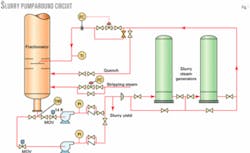
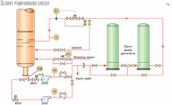
Heat is recovered from the slurry via two vertical shell-and-tube exchangers (steam generators). These exchangers produce 300-psig steam. Slurry flows in series from one exchanger to the other (Fig. 1).
Slurry flows through the tube side of each exchanger and water circulates through the shell side. Tubes are carbon steel, are 16 ft long, have a 1 in. ID, and are configured into a six-pass arrangement.
Total flow rate of slurry through these exchangers is typically 55,000-60,000 b/d, which results in a tube velocity of 6-7 fps.
The clean tube-side pressure drop is about 10 psi/exchanger. Slurry entering the lead exchanger is 650-690° F. and slurry leaving the lag exchanger is typically 450-500° F. The total duty is typically around 100 MMbtu/hr.
Most of the slurry in the steam generators desuperheats and condenses the hot hydrocarbon vapors entering the main fractionator; however, some of the slurry leaving the steam generators flows directly to the bottom of the main fractionator (Fig. 1).
This stream is a "pool quench" and subcools the liquid in the main fractionator's bottom. The main purpose of the pool-quench stream is to reduce coke formation.
Without this quench, the slurry temperature in the main fractionator's bottom would exceed 700° F.
Slurry is pumped through a primary and spare centrifugal pump. Each pump has separate suction piping that originates from a single boot at the main fractionator's bottom. The pumps do not have suction screens.
Slurry quench enters the main fractionator through a 4-in. nozzle. Because there is no distributor, the degree of mixing in the main fractionator's bottom is unknown.
Slurry in the fractionator's bottom may experience zones with different temperatures due to poor mixing. The bottoms temperature indicator is in the boot at the main fractionator's bottom.
The refiner controls the slurry quench flow rate using a manually operated globe valve. Operators adjust the valve to maintain a target temperature at the main fractionator's bottom.
The target temperature is actually a range of temperatures. In 1999, the target was 650-690° F. for normal operations. During start-ups and unit upsets, the bottoms temperature can go much lower. Other criteria could set the slurry quench flow rate, but targeting a bottoms temperature range is convenient.
A remotely operated valve controls the slurry pumparound flow rate excluding the quench. This valve's set point is an operator-specified flow rate.
The average residence time of slurry in the pumparound circuit is about 4 hr. The total volume of the slurry pumparound circuit is 270 bbl and the slurry yield averages 1,300 b/d.
Even though slurry in the main fractionator bottom is subcooled, the refiner injects stripping steam into the tower's bottom. Stripping steam has a noticeable impact on the slurry flash point. The stripping steam flow rate is 2,000 lb/hr.
History of slurry fouling
The lead slurry exchanger has an extensive history of coke deposits that cause tube plugging.
In 1987, this exchanger was removed from service 16 times due to plugging. The refiner usually cleaned the tubes by hydroblasting them. In 1988, the exchanger was cleaned six times due to coke deposits.
About 10 years ago, refinery personnel decided to inject a chemical antifoulant to reduce slurry fouling. The antifoulant was injected into the slurry pool quench flowing back to the main fractionator. This antifoulant was still used as late as 1999, and the cost was approximately $100,000/year.
By 1999, Marathon's maintenance department was cleaning the lead exchanger every 6 months due to excessive pressure drop across the tubes. The pressure drop was due to coke deposits that plugged the tubes.
February 1999
The lead slurry exchanger was cleaned in November 1998. This exchanger had been in service for more than 6 months, and this particular cleaning was uneventful.
After placing the exchanger online, however, the unit engineer began to notice an unusually rapid reduction of the heat-transfer coefficient. Operators compensated for this reduced heat transfer by increasing the slurry pumparound and the top reflux flow rates.
In mid-December 1998, the unit engineer decided to maintain a strict main fractionator bottoms temperature of less than 670° F. Before then, no strict maximum temperature was maintained and the slurry temperature occasionally exceeded 690° F.
In January 1999, the pressure drop across this exchanger began to increase. As the pressure drop increased, the pumparound control valve automatically opened wider to maintain a set flow rate. The operators manually opened the quench valve to control the main fractionator bottom temperature.
When the pressure drop increased even more, the operators eventually had to reduce the pool quench flow rate to force more oil to the desuperheating zone.
In late February, the operators had to reduce the FCCU charge rate for maintenance. The refiner decided to clean the lead exchanger at that time.
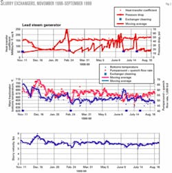
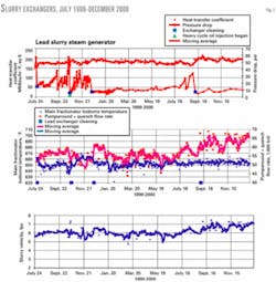
Fig. 2 shows the lead exchanger pressure drop, heat exchanger coefficient, main fractionator bottoms temperature, total slurry flow rate through the heat exchanger (slurry pumparound plus quench), and slurry velocity through the heat exchanger.
Pressure drops in Fig. 2 are corrected to a constant slurry flow rate of 55,000 b/d. Heat-transfer coefficients in Fig. 2 have not been corrected for slurry velocity through the exchanger.
An increasing pressure drop and stable heat-transfer coefficient usually indicate plugged tubes. A falling heat-transfer coefficient can indicate that an insulating film layer is coating the tubes.
The maintenance department found hard coke deposits plugging the tubes during an inspection in late February 1999. A film layer was not readily visible. The lead slurry exchanger was then hydroblasted and returned to service.
null
June 1999
By late March 1999, the unit engineer once again noticed an increasing pressure drop in the lead slurry exchanger. This time, however, the heat-transfer coefficient was stable (Fig. 2).
Through trial-and-error, the operators discovered that idling the exchanger for 10 min would temporarily reduce the pressure drop through the lead exchanger. They would simply bypass the exchanger for 10 min and then return the exchanger to service.
The coke trap was installed at the Texas City refinery in December 2000 (Fig. 4).
The saw-tooth pressure drop curve in Fig. 2 shows that this was effective for only a limited time.
As the pressure drop increased, the slurry pumparound control valve opened wider to maintain a set flow rate. This control valve is typically 80-85% open for normal operations and has linear flow characteristics.
By June, the pressure drop was more than 40 psi, and the main fractionator bottom temperature was increasing due to the reduced flow rate of the slurry oil pumparound. The heat-transfer coefficient never deteriorated.
In late June, the refiner removed the lead exchanger from service and inspected it. Once again, maintenance workers found hard coke deposits plugging the tubes. The exchanger was again hydroblasted and returned to service.
July 1999
On July 20, 1999, operators noticed a sudden increase in the pressure drop across the lead slurry exchanger. The pressure drop increased 17 psi on that day.
Once again, the refiner planned to clean this exchanger before the main fractionator bottoms temperature increased. During the last week in July, the exchanger was isolated and inspected. Once again, coke deposits were plugging the tubes.
No significant deterioration of the heat-transfer coefficient was observed. The exchanger was hydroblasted and returned to service.
Recommendations
RMS Engineering Inc. suggested that the refiner, to mitigate fouling:
- Maintain a relatively low main fractionator bottoms temperature using the slurry quench. The target temperature is unit specific and no given temperature will satisfy all units and feedstocks. The quantity of pool quench sent to the main fractionator bottom will limit the target temperature.
Undercutting the light cycle oil into slurry was not recommended. This is too expensive due to the relatively large price differential between these products.
- Inject light or heavy cycle oil into the lead slurry exchanger. This can sometimes reduce fouling. Injecting 3-5 vol % of the total flow rate of slurry pumparound and pool quench should be adequate.
- Install a coke trap between the main fractionator bottom and inlet to the lead slurry exchanger. A coke trap is simply a filter basket designed to capture coke particles.
Operations and engineering personnel decided to implement the first two items as soon as possible. The coke trap required more time to implement.
In August 1999, operations personnel targeted a main fractionator bottoms temperature of 650° F. and planned to inject heavy cycle oil into the lead slurry exchanger. Heavy cycle oil was more accessible than light cycle oil and would require only minor piping modifications that could be installed on the run.
In October 1999, the piping modifications for 3,000 b/d of heavy cycle oil injection were completed.
null
August 1999-September 2000
Fig. 3 shows the lead slurry exchanger's heat-transfer coefficient, pressure drop, and cleaning dates.
In February 2000, the refinery discontinued injections of slurry antifoulant. This saved the refinery approximately $100,000/year.
The next several cleanings occurred in:
- Late October 1999. This cleaning occurred shortly before heavy cycle oil injection. The FCCU charge rate was reduced for other reasons several days before cleaning this exchanger; therefore, the main fractionator bottoms temperature was slightly lower than usual. Maintenance found coke deposits plugging the tubes.
- Mid-December 1999. This cleaning occurred after heavy cycle oil injections began. Once again, the exchanger was cleaned due to an excessive pressure drop.
Early September 2000. The exchanger was cleaned due to excessive pressure drop. This time, the exchanger achieved a 9-month run since the previous cleaning.
Coke trap
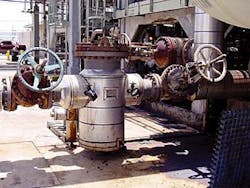
In September 2000, Marathon decided to install a coke trap (Fig. 4). The filter basket was made from 16-gauge carbon steel and had 1/8-in. diameter holes. The pressure drop across the clean basket was less than 1 psi. Maintenance personnel selected carbon steel for the coke trap and basket, but most other refiners should use an alloy.
The coke trap was placed into service in December 2000; total installed cost was less than $100,000.
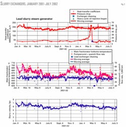
Fig. 5 shows that, from September 2000 to February 2002, the lead exchanger experienced no fouling. The pressure drop across the coke trap was less than 5 psi during this entire time period. Marathon never had to open the trap to remove coke.
In March 2002, however, the lead and lag exchangers began to experience increased pressure drops with stable heat-transfer coefficients. The unit engineer elected to clean the lag exchanger first because it was experiencing the greater pressure drop.
In the lag exchanger, maintenance personnel found the typical coke deposits observed previously. This was unsettling because the coke trap should have captured all coke particles large enough to plug the exchanger tubes. The lag exchanger was hydroblasted and returned to service.
In the meantime, the pressure drop across the lead exchanger continued to increase. Maintenance personnel planned to clean the lead exchanger and inspect the coke trap.
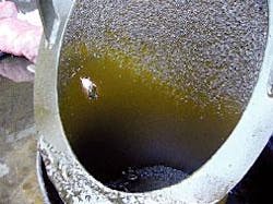
They opened the coke trap and found three holes in the basket. Fig. 6 shows the largest hole with a piece of coke wedged in it. The other smaller two holes were in the bottom of the basket.
Maintenance again found familiar coke deposits in the lead exchanger. They hydroblasted the exchanger and returned it to service. Holes in the coke trap basket were patched, and the coke trap was returned to service.
The refiner never conclusively determined the cause of the holes. Marathon purchased a new basket, fabricated from 3/16-in. thick carbon steel with a hole diameter of 1/4 in.
Fouling symptoms, mitigation
Two effects in the slurry heat exchangers indicated slurry fouling at the Texas City refinery: coke deposits plugging the tubes and deterioration of the heat-transfer coefficient. These symptoms occurred both together and independently.
Maintaining a relatively low bottoms temperature can mitigate the deteriorating heat-transfer coefficient. The relationship between fouling, bottoms temperature, and slurry velocity through the exchanger is unknown; however, for this refinery, a maximum bottoms temperature of 650-655° F. with a minimum slurry velocity of 6-7 fps was sufficient to prevent deterioration of the heat-transfer coefficient.
These values are strictly empirical and are probably unit specific. The required bottoms temperature is especially unit specific because the degree of mixing in the main fractionator bottom is unknown.
The last time the slurry exchangers experienced a significant loss in the heat-transfer coefficient was in December 1998. This was before the maximum bottoms temperature was lowered to 670° F. in mid-December 1998, and then 650° F. in August 1999.
In addition, the lag slurry exchanger never experienced a significant reduction in heat-transfer coefficient except in November 1998, when this exchanger was in the lead position while the other exchanger was cleaned.
Feedstock properties undoubtedly impact slurry-fouling tendencies. Some feeds have a greater fouling tendency than others.
Coke deposits probably form in the main fractionator or in the vapor line extending from the reactor to the main fractionator. These deposits can intermittently break away from the walls of the vapor line or main fractionator and become caught in the slurry pumparound exchangers.
We are currently studying the benefit of heavy cycle oil injections. In August 2002, heavy cycle oil injections into the lead exchanger were discontinued. No negative impacts were observed as of September 2002; however, more time is needed for this study.
Based on a presentation to the NPRA Annual Meeting, Mar. 23-25, 2003, San Antonio.
The authors
Garth Walker is a senior process engineer with Marathon Ashland Petroleum LLC, Texas City. He has worked on the FCCU for the past 5 years and is responsible for unit monitoring, optimization, troubleshooting, and preliminary development of value-added projects. Walker previously worked for British Petroleum PLC and Indian Refining Co., Lawrenceville, Ill.
Reza Sadeghbeigi is the president of the RMS Engineering Inc., Houston. He has 26 years' experience in various aspects of cat cracking at major and independent oil companies focusing on technical services, troubleshooting, process design, and project management including major FCC revamps. Sadeghbeigi holds a BS in chemical engineering from Iowa State University and an MS from Oklahoma State University. He is a registered professional engineer in Texas and Louisiana.
