Study evaluates design considerations of larger, more efficient liquefaction plants
Study evaluates design considerations of larger, more efficient liquefaction plantsRecent trends in the design of LNG production facilities focus on train sizes of 3-8 million tonnes/year (tpy). We conducted a study to evaluate potential advantages and design solutions inherent with the larger pieces of equipment needed for these higher-capacity LNG plants.
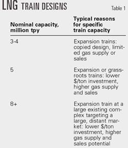
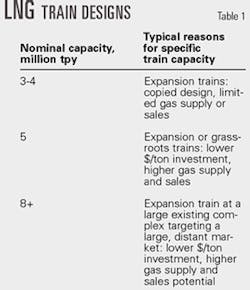
Notwithstanding shipping and market acceptability, LNG train designs in the next decade appear to fall into three groups: nominal capacities of approximately 3-4 million tpy, 5 million tpy, and 8+ million tpy.
Several 3-4 million tpy trains have been built in the past 2 years. Two 5 million tpy LNG trains are under construction; the largest is Atlantic LNG's Train 4, which has a nominal capacity of 5.2 million tpy.
Table 1 shows likely reasons for building a specific plant size. These three LNG train design capacities may coexist in future projects; different projects will find advantages in a specific size.
Developers and designers of large-capacity trains want to know how a single large LNG train will compare in cost and operational flexibility to that of two smaller 50% trains.
Owners of larger LNG facilities keep looking for ways to lower costs through the benefits of economies of scale.
As export capacity grows, owners tend to have fewer concerns for maximum LNG train size, especially when the design includes a "two-trains-in-one" reliability concept that allows the LNG train to operate at 60-80% capacity even with one of the gas turbine drivers down temporarily.
Outstanding safety, reliability, and high operating factors of LNG plants also give owners the confidence to build larger trains.
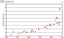
Last year (OGJ, Aug. 19, 2002, p. 60), we showed the acceleration in train size for projects in engineering, procurement, and construction, for capacities up to about 5.2 million tpy.
We added proposed LNG trains to create Fig. 1, including trains with nominal capacities of 7-8 million tpy, which could come on stream before 2010 in Qatar.
New LNG plants
International LNG trade continues to expand rapidly. There were only two new grassroots LNG plants built in the 1980s. In the 1990s, six new grassroots projects were built in Malaysia, Oman, Qatar, Nigeria, and Trinidad and Tobago. Owners also revamped and expanded existing facilities during the 1990s.
Seven additional grassroots plants are currently in, or are about to enter, engineering and construction: two projects in Egypt—one at Idku and one at Damietta—and projects in Australia, Equatorial Guinea, Indonesia, Norway, and Russia.
Expansion continues in new plants such as those in Nigeria and Trinidad and Tobago; additional new projects are proposed in Nigeria, Angola, Qatar, and other locations.
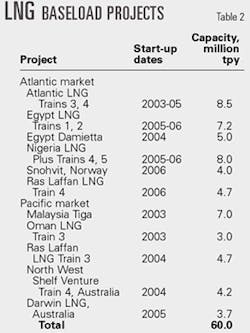
The total LNG capacity currently in engineering and construction is about 60 million tpy, or about 50% of existing worldwide baseload LNG capacity (Table 2). If all these projects come on stream, LNG trade could reach a worldwide volume of more than 180 million tpy by 2010.
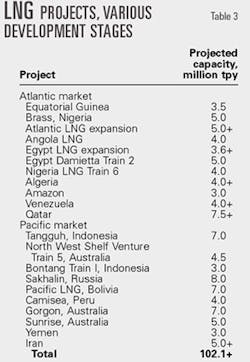
Table 3 shows other projects that could soon enter the engineering and construction stage but are constrained by market availability, partner alignment, or other issues. These projects total more than 100 million tpy of LNG. Some of these projects will be delayed by at least 10 years before the market can catch up with potential supply.
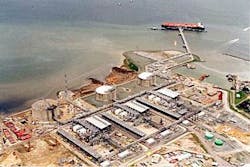
Trinidad Atlantic LNG Train 4, at a nominal capacity of 5.2 million tpy, is the largest LNG train under construction in the world (Fig. 2). A similar capacity LNG train, about 5 million tpy, is also under construction at Damietta, Egypt.
New technologies
A recent study by BP PLC evaluated a proposed new liquefaction technology, Liquefin, which uses dual mixed refrigerants and aluminum plate fin heat exchangers.1
The study authors evaluated several cases, including one that used two Frame 7 or Frame 9 gas turbines, each driving a refrigerant compressor, with waste-heat recovery. Plant electricity is generated from steam.
Another case study used four LM 6000 gas turbines with inlet air cooling to drive the compressors. Yet another case study used large electric drives of up to 100 Mw for the refrigeration compressors. The authors concluded that there are opportunities to lower costs and reduce CO2 emissions from larger-train LNG plants.
Air Products and Chemicals Inc. developed the AP-X process by adding a nitrogen expansion cycle to the pro- pane precooled, mixed-refrigerant process.2 The nitrogen cycle reduces the load on the limiting mixed-refrigerant service to about 60%; this allows capacities of up to 8 million tpy.
The ConocoPhillips-Bechtel LNG Product Development Center has developed large LNG train designs using the Phillips optimized cascade LNG process.
null
Operating LNG trains with this process use Frame 5 series gas turbines as compressor drivers. Recently, owners of the Darwin LNG project in Australia chose to install LM2500+ aeroderivative gas turbines.
The Phillips process dual-shaft Frame 5 series driver configurations provide robust LNG producing facilities with high on-stream factors; however, in some cases, Frame 7EA and Frame 9E industrial gas turbines, combined with steam turbines and electric motors, can provide attractive alternatives for large liquefaction plants.
The Frame 7EA industrial gas turbine is a 115,330-hp (85.9 Mw), ISO-rated, single-shaft turbine that operates at 3,600 rpm.
The Frame 7EA was originally designed for electrical generation service rather than for mechanical drive service; therefore, it has limited rotating-speed flexibility. This lowers the operating flexibility of the LNG process.
The ConocoPhillips Kenai LNG facility was the first to use single-shaft industrial gas turbines. It has operated for more than 33 years with an availability, production efficiency, and turbine reliability of 98+%, 95+%, and 99+%, respectively.
Driver, compressor configurations
Three of the case studies evaluated by the ConocoPhillips-Bechtel LNG PDC are covered in this article.3
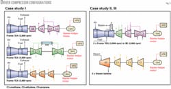
Case I used three Frame 7EA turbines for the refrigerant cycles, whereas Case II used two Frame 7EA gas turbines equipped with waste-heat recovery and two parallel steam turbines.
Case III was similar to Case II, but it used Frame 9 gas turbines instead of Frame 7 turbines.
Fig. 3 shows the different configurations. The driver-compressor arrangement in Case I required a gearbox between the gas turbine and the propane compressor to reduce the nominal speed from 3,600 rpm to about 2,400 rpm.
Unlike split-shaft gas turbines, single-shaft turbines like the Frame 7EAs require starting assistance beyond what the vendor typically provides. For the driver-compressor configurations, we had to equip the Frame 7EA with a starting motor that would double as a helper motor to achieve the desired LNG production rate.
The motor size rating depends on the refrigerant pressure in the piping, compressor system, and respective isolation valves, and the incremental power required to achieve the target LNG production rate. Starter-helper motors can range from 5 to 30 Mw depending on the facility's design premise.
System dynamics
We hired an independent dynamic- modeling expert to simulate start-up capabilities of the proposed configurations. The modeler used a full-scale plant dynamic simulation to test several scenarios. The goals were to demonstrate start-up and controllability and operability of the LNG plant during upset conditions.
Unlike the Frame 5D gas turbine, the Frame 7EA requires external assistance during start-up, especially if the respective compressor is to remain pressurized.
There are two primary methods for starting large, single-shaft-frame-type industrial gas turbines coupled to compressors. The primary mechanism for starting single-shaft gas turbines is to combine an electric motor with a variable-frequency drive for low-speed, high-torque starting. The other method, a steam turbine, is equally effective but not as common.
We chose the motor starter for these studies.
For the propane and ethylene refrigerant cycles in the Phillips process, our studies confirmed the starting motor and recycle valve sizes relative to system starting pressures, and the cooling mechanism.
We also performed dynamic simulations of the plant process, as well as trip scenarios such as a blocked outlet valve, loss of refrigerant cooling, plant emergency trips, etc. The results allowed optimization of the control scheme for operating upset conditions.
Economies of scale
During the past few years, the LNG community has focused on economies of scale.
Plant capital costs generally increase to the 0.65 power as capacity increases, and indications are that this is also the case for LNG. Many have debated, however, that this cost reduction may reach a plateau around 5 million tpy due to maximal capacities in critical equipment such as gas compressors, control valves, etc.
As part of the study, we examined the availability, cost, and projected reliability of critical pieces of equipment:
- Compressors. We solicited GE Power Systems-Nuovo Pignone and Elliott Co. for suitable compressor suggestions and designs. We evaluated the designs submitted by both manufacturers, especially regarding flow coefficients, rotor dynamics, and relative mach numbers.
We found that compressor size will not be a limiting factor for LNG trains using the Phillips process for the range of capacities we evaluated.
- Piping. The largest gas pipe size ranged from 72-in. to 84-in. diameter for velocities of 30 m/sec for the low-pressure propane and ethylene compressor inlets. These gas velocities are acceptable in terms of erosion, vibration, and noise considerations. Piping in these sizes is readily available.
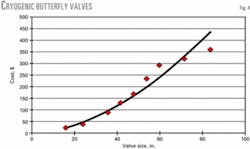
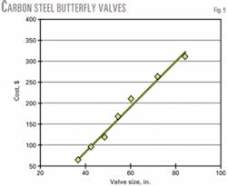
Fittings and valves. We considered cryogenic and carbon steel butterfly valves up to 84-in. ID in this study. Maximum pipe diameter was 120 in. Figs. 4 and 5 show that the increased cost for carbon steel and cryogenic valves is a function of size.
- Vessels and exchangers. Process equipment sizes increase with production rates. We found no technical constraints for vessel size, fabrication, or wall thickness. Transportation, however, could be an issue for larger vessels and exchangers especially if rail or highway transportation is required.
The economics of a particular plant location are ultimately the deciding factor for selection of vendors or transportation method.
- Cold box. We also evaluated cold box sizes, fabrication, and shipping. One limit is the size of the furnace used to fabricate the brazed-aluminum heat exchangers. This limit can be resolved using multiple, smaller units to achieve the required duty.
As with vessels, the cold box's size for a larger LNG plant could lead to transportation problems for the weights and dimensions of large boxes. We are conducting additional studies to address these issues.
Capital cost, efficiency, emissions
We developed a cost estimate for each of the configurations. We used a detailed takeoff for most bulk items, a combination of in-house pricing from recent projects or vendor quotes for major equipment, and budgetary pricing for the combustion turbine generators and process compressors. We developed and compared total direct costs for each configuration for consistency.
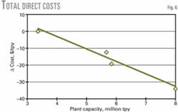
Fig. 6 shows that unit cost keeps decreasing with higher LNG production capacities.
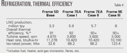
Table 4 summarizes the refrigeration power requirements and plant overall thermal efficiencies for the respective case studies. Differences in heat rate between the gas turbine drivers and the addition of waste-heat recovery provide higher thermal efficiencies.
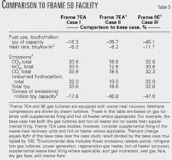
Table 5 compares emission data to that of a Frame 5D Phillips process facility.
Process selection
Selection criteria for LNG plant owners and designers include:
- Capital and operating costs. Capital costs decrease as LNG production capacity increases. A single-train configuration with a direct driver and no waste-heat recovery gives the lowest capital cost/million tpy at a specific capacity.
Operating costs, however, for a similar-size plant that includes waste-heat recovery will be lower. Each facility must evaluate the specific priorities and economic data to determine which method best meets the objectives.
- Emissions. Larger industrial gas turbines tend to be more efficient and have lower emissions. Using waste-heat recovery to produce steam to drive one or more refrigeration trains reduces the gas consumed for fuel, and the emissions for a given capacity rating.
Aero-derivative gas turbines have higher efficiencies than industrial frame machines. General Electric Co. recently announced a new version of the Frame 5 gas turbine (5E), which will have a higher efficiency than the 5D machine.
Electric drives that use electricity produced from a combined-cycle power plant can also raise efficiency and lower emissions. We are currently studying these configurations.
- Operability. We found no significant issues regarding operability with the larger drivers and compressors. The Frame 7EA drivers have a narrow band of speed control, a factor that the system's design must compensate for. We performed dynamic simulations to ensure there were no operability issues.
- Two-trains-in-one concept. ConocoPhillips-Bechtel LNG designs typically use the two-trains-in-one concept. This allows the LNG plant to operate at about 70% capacity even when one of the gas turbine drivers trips.
Acknowledgment
We acknowledge the assistance of Sergio Buoncristiano and Massimo Camatti of GE Power Systems-Nuovo Pignone, and Randy Byrd and Aaron York of Elliott.
References
1. Sawchuk, J., Jones, R., and Ward, P., "BP Big Green Train – The Next generation in LNG," Gastech 2002, Oct. 13-16, 2002, Doha, Qatar.
2. Roberts, M., Petrowski, J., Liu, Y.-N., and Bronfenbrenner, J., "Large capacity single train AP-X hybrid LNG process," Gastech 2002, Oct. 13-16, 2002, Doha, Qatar.
3. Avidan, A., Richardson, F., Anderson, K., and Woodard, B., "LNG Plant scale-up can cut costs further," Fundamentals of the Global LNG Industry 2001, Petroleum Economist, London.
The authors
Amos A. Avidan is principal vice-president, Bechtel Fellow, and manager of petroleum and chemicals technology and development at Bechtel Corp., Houston. He manages Bechtel's technology centers of excellence, which include LNG and gas plants, refining, chemicals, and technology licensing. Before joining Bechtel, he was with Mobil Corp. for 20 years. Avidan holds a PhD in chemical engineering from City University of New York.
Wayne Varnell is an area project engineer on the Alba Phase 3 LNG project for Bechtel Corp., Houston. He has 30 years' experience in various major refinery, chemical, and power generation projects. Varnell holds a BS in nuclear engineering from Texas A&M University.
Bobby Martinez manages the LNG Product Development Center at ConocoPhillips-Bechtel Houston. He holds a BS in chemical engineering and a BS in chemistry from New Mexico State University and is a registered professional engineer in Texas.
