Pipeline rehab responding to regulatory pressures, technological advances
As regulatory and safety bodies, such as the US Department of Transportation's Office of Pipeline Safety, increasingly emphasize risk management as a tool in pipeline operation and maintenance, inspection tools and repair strategies will continue to play greater roles in ensuring pipeline integrity.
This article will describe historical pipeline pigging developments, techniques, and applications, as well as repair techniques employed throughout the pipeline industry.
It will highlight current techniques and present research trends for future pipeline integrity inspection and rehabilitation techniques.
A recent trend has been rehabilitation and integrity monitoring of existing pipelines using high-resolution magnetic flux leakage (MLF) technology as one of the primary inspection tools. The near future will see development and improvement of in-line inspection (ILI) tools for detection of cracks and stress corrosion cracking (SCC).
In addition to MFL, pipeline-integrity inspection now includes inertial and ultrasonic tools.
Repair techniques have moved from simple grinding of defects or cut-outs to modern sleeving techniques and development of composite sleeves.
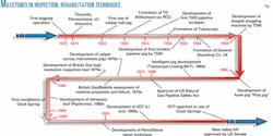
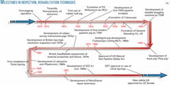
Fig. 1 shows some of the key developments in pipeline inspection technology and rehabilitation from 1870 to the present. These developments in integrity inspection and rehabilitation mostly result from an aging infrastructure and some safety-related issues that have pre-occupied the industry over the last 20 years.
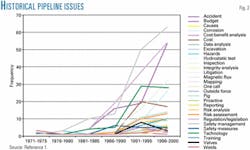
Fig. 2 shows how safety management has dramatically increased in the past 10 years and currently leads the issues facing the industry.1 Although this statistic was generated for the US, it is also relevant to the pipeline industry worldwide.
Table 1 shows how there is a trend toward the use of higher-grade steel and increased operating pressures, from 200 kPa in 1910 (up to 16-in. OD) to 15,000 kPa in the 1990s (up to 56-in. OD).
Correspondingly, low-grade steel was used in the early 1900s and higher-strength steel (X-80) by the 1990s. The trends are toward X-100 and alternative composite materials for future projects.2
Inspection technologies
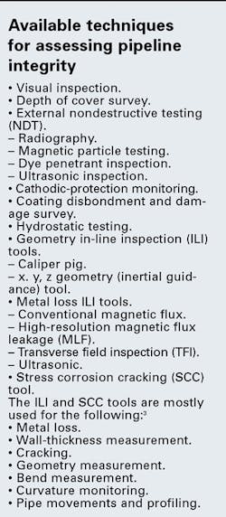
Several techniques are available for assessing the integrity of pipelines. The accompanying box lists the most common.
MFL tools detect metal loss within pipe wall, pipe property changes, and ferrous materials adjacent to pipe walls. On the other hand, transverse field (TFI) tools detect such axial anomalies as longitudinal seam weld cracks and corrosion.4
ILI and SCC technologies have changed pipeline inspection from a mere caliper ID measurement to detecting corrosion anomalies and cracking.5
Each technique will have maximum benefit if the extent of the integrity problem is recognized and the scope of inspection to be performed is well defined. ILI inspection provides meaningful results if defect specifications and inspection requirements are matched accordingly.
Defect assessment
Defects appear in the pipeline in many forms. The operator and industry standards dictate which defects need to be repaired and to what extent. Possible defects include the following:6
- Corrosion.
– General.
– Pitting.
– Erosion. - Gouge (possibly caused by mechanically induced damage).
- Mechanical damage (dent with a gouge).
- Dents.
– Smooth (localized distortion).
– Kinked (rapid change of contour). - Cracks (planar two-dimensional defect with fracture).
- Lamination (manufacturing defect).
- Spalling (severe abrasion).
- SCC (stress corrosion cracking).
- Perforations (causing rupture and leaks).
Repair, rehabilitation
Pipeline repair and rehabilitation traditionally have been conducted by simple grinding, installing of a mechanical sleeve, application of a coating, or cutting out.
In the 1970s and 1980s, engineering sciences from various design and manufacturing fields started to make significant advances with coatings and composite materials.
The 1980s was also a time of increased industry-sponsored research and development of technologies to help maintain and improve safety and operation of pipelines. Scientists and engineers collaborated to evaluate different pipeline repair and inspection methods from the more-traditional methods previously mentioned. The result was development of new and more-advanced inspection technologies and products.
It wasn't until the late 1980s, however, that the pipeline industry started applying some of these new concepts to rehabilitation and repair. For example, epoxy composition-filled sleeves became commercially available for installation during that time.
The 1990s saw the development and growth of more-advanced composite coating and repair techniques. Issues such as economic feasibility, safety, performance, anticorrosion, and ability to make in situ repairs have been keys in their popularity. Results have been impressive, and regulatory authorities are approving some of these new composite repair methods as permanent repairs (OGJ, May 8, 2000, p. 65).
Permanent repairs for some corrosion and mechanical defects are now done without welding or cutting the pipeline. That increases safety and significantly lowers environmental risk. PRCI Document L51716 is an excellent reference to different repair techniques.7
Collaboration within the pipeline industry continues to provide safer, faster, environmentally conscious, and more cost-effective alternatives for repairing damaged pipelines. Following are some traditional and new repair methods available:
•Grinding repair. Grinding does not involve application of any fitting to the pipeline. Grinding repairs can be performed to superficial forms of gouges, corrosion, abrasions, some laminations, and some cracks.
The procedure involves use of a low-powered angle grinder to produce a smooth profile and thereby eliminate any stress point. It is a highly skilled procedure that must be carried out in accordance with strict guidelines to avoid the removal of too much metal (< 0.5% wall thickness).
•Full encirclement split-sleeve repair. By forming a snug fit around the carrier pipe, a properly installed split sleeve will support a defective area such as a gouge or dent and gouge. The longitudinal seams are welded, and if total containment is required, fillet welds are directly performed at each end.
Split-sleeve installation is highly specialized. Application temperatures are important during welding to avoid potential hydrogen-induced cracking. If the sleeve is subject to significant cyclic pressures, care must be taken to avoid potential fatigue cracks.
If gouges or dents with gouges are being repaired, the dent must be reinforced and filled with epoxy to prevent bulging.
•Pipe replacement or cut-out. The preferred method of repair for many pipeline operators, replacement or cut-out removes the defective section and replaces it with new problem-free pipe. It is, however, one of the most expensive options, especially when considering the environment, lost product, and outage downtime.
•Stopple and bypass. One way to achieve continued flow during replacement of a section of defective pipe is to perform a stopple and bypass. Numerous hot-tap fittings must be attached to the pipeline, and it extremely expensive. For a simple, two-position stopple operation, nine fittings are required, all of which must be welded to the live pipeline.
•Composition sleeve repairs. Epoxy composition-filled reinforced sleeve repairs are relatively new compared to the more-traditional repair methods, although some have been in use for over 15 years.
This repair is made with two oversized sections of semicircular steel shells joined together to encircle the damaged area, leaving a circular gap. This gap is sealed at each end of the sleeve—using an easily applied, fast-setting material—and then filled at a very low pressure with a high stiffness, epoxy-based compound.
There is no welding to the pipeline. Tests show it provides good bulging restraint for the defective area and performs well under internal pressure loading and fatigue cycles.
•Clock Spring repair. The Clock Spring pipeline reinforcement system is a coil wrap of high-strength composite material.6 This system, which consists of a fiberglass and polyester composite material coiled with adhesive in layers over a filler, reinforces steel pipe that has certain nonleaking defects.
According to tests and analyses by the Gas Research Institute (GRI), when properly installed, the system permanently restores the pressure-containing capability of the pipe.
The defect (corrosion, mechanical damage, or dent) is filled with an adhesive filler to help with support and load transfer prior to the Clock Spring installation.
It is not recommended for internal defects, sharp crack-like defects, or (because of its unidirectional structure) girthweld-circumferential defects.
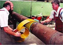
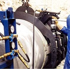
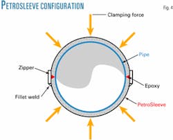
•PetroSleeve repair. The PetroSleeve repair system was developed by Robert Smyth & Associates, Calgary, in the early 1990s to provide a method permanently to repair anomalies on an operating pipeline—such as stress corrosion cracking, dents, corrosion, or mill defects—while the pipeline remained in operation (Figs. 4 and 5).8
It supports and reduces the stress in the steel adjoining the defect so that the defect is arrested from growing or deteriorating. Installation of a PetroSleeve reduces the stress state in the material surrounding the defect. This reduction in stress state removes the possibility for crack extension.
A PetroSleeve can eliminate flexing in the pipe material compresses the stress state in the material surrounding the defect. These two actions help eliminate fatigue, crack extension, and rupture.
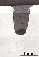
Fig. 6 shows how on one repair crack extension was arrested after a compression sleeve had been installed. The testing included sleeving a 48% crack in the ERW (electric-resistance welded) seam and subjecting it to 36,500 pressure cycles (100-1,168 psi).
Following this cycling, metallographic examination found no evidence of extension to the original crack prior to installation of PetroSleeve.
The same cyclic and metallographic testing was performed on a 12-in. long parabolic slot, 70% through wall in the ERW seam. Again, no evidence of defect extension was found.9
About 1,600 PetroSleeves have been installed to repair cracks, corrosion, dents, and arc burns.
•StrongBack composite wrap repair.
The StrongBack system consists of a tape wrap (such as glass fiber) made up of proprietary load-transfer and coating agents based on a unique blend of liquid epoxy polymer and curing agents.
This wrap can be applied to wet surfaces (including underwater). The wrap is able to displace water from wet surfaces in order to make a permanent bond. This tape wrap-reinforcement system can be used to repair either relatively low levels of corrosion or mechanical damage.
•Armor Plate repair. Armor Plate pipe wrap is another structural pipe repair system that uses multipurpose fiberglass-epoxy wraps and curing agents. It consists of a woven fiberglass-epoxy resin that creates a monolithic composite pipe reinforcement.
The composite material has been proven by extensive lab testing with the basic materials over 30 years of field experience in the petrochemical and related industries. It is similar to StrongBack, in that it is considered a good reinforcement system to repair relatively low levels of corrosion or mechanical damage. Its hardening agent is chemical rather than water, however.
Integrity-management programs
Managing pipeline-system integrity aggressively is essential for all owners and operators of hazardous liquid or natural gas pipelines. Historically, pipeline-integrity programs have been managed internally by individual companies and tailored to their unique systems.
Since the late 1990s, the US DOT has ensured that US liquid pipeline companies have integrity-management programs in place that define the processes a company utilizes to improve pipeline safety.
API Standard 1160, "Managing System Integrity for Hazardous Liquid Pipelines," was developed to help operators comply with newly established federal rules regarding pipeline-integrity management in high consequence areas (HCAs).10
API 1160 includes guidance for compliance with these US DOT requirements, and it can be applied to other non-US-operated pipelines as well. The following guidelines used to establish API 1160 are applicable to all pipeline systems:
- Build-in integrity from the beginning.
- Use trained people and defined processes to operate facilities.
- Make integrity-management programs flexible.
- Integrate information.
- Make risk assessment key and continuous.
- Understand and utilize new technology.
- Use a third-party to evaluate integrity-management systems.
An integrity-management program, as defined by DOT, is a documented set of policies, processes, and procedures that includes, at a minimum, the following elements:
- A process for determining which pipeline segments could affect an HCA.
- A baseline assessment plan.
- A process for continual integrity assessment and evaluation.
- An analytical process that integrates all available information about pipeline integrity and the consequences of a failure, repair criteria to address issues identified by the integrity assessment method, and data analysis.
- A process to identify and evaluate preventive and mitigative measures to protect HCAs.
- Methods to measure the integrity-management program's effectiveness.
- A process for review of integrity-assessment results and data analysis by a qualified individual.
The key to any integrity-management program is the establishment of a baseline assessment plan with the following:
- Identify all pipeline segments that could affect HCAs.
- Specify the integrity assessment method(s) for these segments (acceptable methods include, internal inspection, hydrostatic pressure testing, or equivalent methodology).
- Prioritize, based on risk assessment.
- Provide a schedule for assessment.
- Explain the technical basis for integrity assessment method(s) selection and risk factors used in scheduling the assessments.
Integrity-management programs should be reviewed and updated continually. Each review should include methods to measure the program's effectiveness in assessing and evaluating integrity. The risks must be understood, managed, and controlled.
Risk assessment is an integrity-management tool to identify and quantify the risks associated with pipeline operation, so that remedial action can be performed in a timely manner. This is achieved through the ranking of potential risk to safety, environment, and operations.
Although extensive risk assessments are somewhat new to the pipeline industry, other industries, such as the chemical industry, have used risk assessments as a part of their management programs. Many of the practices used in assessing risk in other industries can be applied to the pipeline industry.
The most common risk-assessment methods are failure-probability methods and ranking systems. The most appropriate method depends upon several factors, including system complexity, availability of historical data, and rigor required by the analysis.
Pipeline integrity-management decisions are made much easier by the risk assessment and prioritization process, which establishes a firm, documented basis for expenditures and schedules.
Technology is helping answer many complex questions in respect to safety, reliability, and integrity. It is evident that they will continue to be a top priority for pipeline companies and regulators worldwide for years to come.
Acknowledgment
The authors acknowledge the support of the management of Enbridge Technology Inc. for publication of this article.
References
- Sandoval, A., Beruvides, M., and Wiesner, T., "State of the Art Analysis of Current Research Trends in Pipeline Safety," AIChE Spring National Conference, Apr. 22-26, 2001.
- Mohitpour, M., Glover A., and Trefanenko, Bill, "Technology advances key worldwide gas pipeline developments," OGJ, Nov. 26, 2001, pp. 60-67.
- Uzelac, N.I., "In-Line Inspection Tool to Achieve Pipeline Integrity," First Internet Conference on Pipeline Reliability (PICon), PICon Publication, Mar. 13, 2000. http://www.nrcan.gc. ca/mms/picon-e.htm
- Yasinko, Ed A., Vieth, Patrick H., Dick, Dean D., Nidd, Phil G., and Pierantoni, Troy D., "Platte TFI Program: Innovative Solutions to Hydrostatic Testing," ASME IPC 2000 Conference Calgary, Oct. 1-5, 2002.
- Holden, E., "The Changing Role of Inspection," PII Publication: http://www.piigroup.com/reference_library/papers/papers.html, 1997.
- Hewing, M., "Differing Repair Methods—Options and Benefits," Second Latin American Pipeline Integrity Conference, Puerto La Cruz, Venezuela, August 1999.
- Keifner, John F., Bruce, W.A., and Stephens, D.R., "Pipeline Repair manual," PRCI Catalog L 51716, 1994.
- Smyth, Robert J., "Repairing Pipe Defects (Cracking, Arc Burns, Corrosion, Dents) Without Operational Outages Using the Petrosleeve Compression Sleeve Repair Technique," International Pipeline Conference, Calgary, June 7-11, 1998.
- Smyth, Robert J., "Pressure Cyclic Testing the Petrosleeve to Measure Edge Effects and to Illustrate the Ability of the Sleeve to Prevent Serious Pipe Defects from Failing," 5th Congreso y Expo Internacional de Ductos, Morelia, Michoacán, México, Oct. 18-20, 2000.
- Jaske, C.E., "Managing Pipeline System Integrity: Introduction to API Standard 1160," presented to Pipe Liners Club of Tulsa, January 2002.
Based on a presentation to the International Pipeline Conference Sept. 29-Oct. 3, 2002, Calgary.
The authors
Mo Mohitpour is the president of Tempsys Pipeline Solution Inc. and a principal consultant with Enbridge Technology Inc. involved in projects in Oman, Brazil, and Colombia. He has more than 27 years' experience in engineering, construction, and management of pipeline systems and associated facilities for oil, gas, condensate, batched products, specialty fluids transmission, storage, tankage, and distribution. Mohitpour is a registered professional engineer in several US states and Canadian provinces and is a member of ASME, the Institution of Mechanical Engineers (UK), and the Engineering Institute of Canada.
Mike McManus is a senior engineer at Enbridge International Inc. and currently provides pipeline engineering and technical support for international pipeline projects and operations. He has more than 12 years of oil and gas industry experience in pipeline integrity and maintenance, pipeline operations, planning, and design. He holds a BSc in mechanical engineering from the University of Calgary and is registered professional engineer.
Bill Trefanenko has more than 24 years' experience in the oil and gas pipeline industry involving engineering design, construction, project management, operations, integrity and rehabilitation, maintenance, and management in both owner-operator and engineering consulting companies.
He has managed projects in several countries, including Malaysia, Russia, Argentina, and Chile and has recently managed two planned maintenance contracts with Pemex Exploration and Production in the south and marine zones of Mexico. Trefanenko is currently manager of technology transfer for Enbridge Technology Inc.
